LT8705
APPLICATIONS INFORMATION
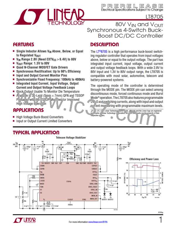
The first page shows a typical LT8705 application circuit.
Aftertheswitchingfrequencyisselected,externalcompo-
where f
is in kHz and R is in kΩ. Conversely, R (in
OSC T T
kΩ) can be calculated from the desired frequency (in
kHz) using:
nent selection continues with the selection of R
and
SENSE
theinductorvalue.Next,thepowerMOSFETsareselected.
Finally, C and C are selected. The following examples
and equations assume continuous conduction mode un-
less otherwise specified. The circuit can be configured
for operation up to an input and/or output voltage of 80V.
43,750
fOSC
IN
OUT
RT =
–1 kΩ
SYNC Pin and Clock Synchronization
TheoperatingfrequencyoftheLT8705canbesynchronized
to an external clock source. To synchronize to the external
source, simply provide a digital clock signal into the SYNC
pin. The LT8705 will operate at the SYNC clock frequency.
Operating Frequency Selection
The LT8705 uses a constant frequency architecture
between 100kHz and 400kHz. The frequency can be set
using the internal oscillator or can be synchronized to an
externalclocksource.Selectionoftheswitchingfrequency
is a trade-off between efficiency and component size.
Low frequency operation increases efficiency by reducing
MOSFET switching losses, but requires more inductance
and/or capacitance to maintain low output ripple voltage.
For high power applications, consider operating at lower
frequencies to minimize MOSFET heating from switching
losses. The switching frequency can be set by placing an
appropriate resistor from the RT pin to ground and tying
theSYNCpinlow. Thefrequencycanalsobesynchronized
to an external clock source driven into the SYNC pin. The
following sections provide more details.
The duty cycle of the SYNC signal must be between 20%
and 80% for proper operation. Also, the frequency of the
SYNC signal must meet the following two criteria:
1. SYNC may not toggle outside the frequency range of
100kHz to 400KHz unless it is stopped low to enable
the free-running oscillator.
2. The SYNC pin frequency can always be higher than the
free-running oscillator set frequency, f , but should
OSC
not be less than 25% below f
.
OSC
After SYNC begins toggling, it is recommended that
switching activity is stopped before the SYNC pin stops
toggling. Excess inductor current can result when SYNC
stops toggling as the LT8705 transitions from the external
SYNC clock source to the internal free-running oscillator
clock. Switching activity can be stopped by driving either
the SWEN or SHDN pin low.
Internal Oscillator
The operating frequency of the LT8705 can be set using
the internal free-running oscillator. When the SYNC pin
is driven low (<0.5V), the frequency of operation is set
by the value of a resistor from the RT pin to ground. An
internally trimmed timing capacitor resides inside the IC.
The oscillator frequency is calculated using the following
formula:
CLKOUT Pin and Clock Synchronization
The CLKOUT pin can drive up to 200pF and toggles at the
LT8705’sinternalclockfrequencywhethertheinternalclock
is synchronized to the SYNC pin or is free-running based
43,750
on the external R resistor. The rising edge of CLKOUT is
fOSC
=
kHz
T
R + 1
T
approximately 180° out of phase from the internal clock’s
8705p
20
For more information www.linear.com/8705

 Linear [ Linear ]