LT3580
APPLICATIONS INFORMATION
(1) SYNC may not toggle outside the frequency range of
200kHz to 2.5MHz unless it is stopped low to enable
the free-running oscillator.
to ~200mV before charging resumes, thus assuring that
the soft-start occurs after every reactivation of the chip.
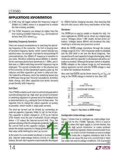
Shutdown
(2) The SYNC frequency can always be higher than the
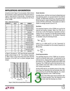
The SHDN pin is used to enable or disable the chip. For
most applications, SHDN can be driven by a digital logic
source. Voltages above 1.38V enable normal active op-
eration. Voltages below 300mV will shutdown the chip,
resulting in extremely low quiescent current.
free-running oscillator frequency, f , but should not
OSC
be less than 25% below f
.
OSC
Operating Frequency Selection
There are several considerations in selecting the operat-
ing frequency of the converter. The first is staying clear
of sensitive frequency bands, which cannot tolerate any
spectral noise. For example, in products incorporating RF
communications, the 455kHz IF frequency is sensitive to
any noise, therefore switching above 600kHz is desired.
Some communications have sensitivity to 1.1MHz, and in
thatcase, a1.5MHzswitchingconverterfrequencymaybe
employed. The second consideration is the physical size
of the converter. As the operating frequency goes up, the
inductor and filter capacitors go down in value and size.
The tradeoff is efficiency, since the switching losses due
to NPN base charge (see Thermal Calculations), Schottky
diode charge, and other capacitive loss terms increase
proportionally with frequency.
While the SHDN voltage transitions through the lockout
voltage range (0.3V to 1.24V) the power switch is disabled
and the SR2 latch is set (see the Block Diagram). This
causesthesoft-startcapacitortobegindischarging,which
continues until the capacitor is discharged and active op-
eration is enabled. Although the power switch is disabled,
SHDN voltages in the lockout range do not necessarily
reduce quiescent current until the SHDN voltage is near
or below the shutdown threshold.
Also note that SHDN can be driven above V or V
as
IN
OUT
long as the SHDN voltage is limited to less than 32V.
ACTIVE
(NORMAL OPERATION)
1.38V
Soft-Start
(HYSTERESIS AND TOLERANCE)
1.24V
TheLT3580containsasoft-startcircuittolimitpeakswitch
currents during start-up. High start-up current is inherent
in switching regulators in general since the feedback loop
LOCKOUT
(POWER SWITCH OFF,
SS CAPACITOR DISCHARGED)
is saturated due to V
being far from its final value. The
OUT
0.3V
SHUTDOWN
(LOW QUIESCENT CURRENT)
regulator tries to charge the output capacitor as quickly
as possible, which results in large peak currents.
0.0V
3580 F06
The start-up current can be limited by connecting an
external capacitor (typically 100nF to 1μF) to the SS pin.
This capacitor is slowly charged to ~2.2V by an internal
275k resistor once the part is activated. SS pin voltages
below ~1.1V reduce the internal current limit. Thus, the
gradualrampingoftheSSvoltagealsograduallyincreases
the current limit as the capacitor charges. This, in turn,
allows the output capacitor to charge gradually toward its
final value while limiting the start-up current.
Figure 6. Chip States vs SHDN Voltage
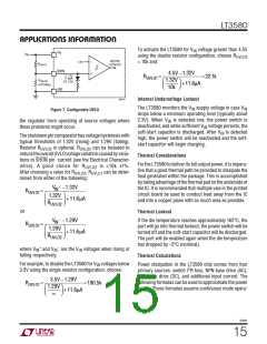
Configurable Undervoltage Lockout
Figure 7 shows how to configure an undervoltage lock-
out (UVLO) for the LT3580. Typically, UVLO is used in
situations where the input supply is current-limited, has
a relatively high source resistance, or ramps up/down
slowly. A switching regulator draws constant power from
the source, so source current increases as source voltage
drops. This looks like a negative resistance load to the
source and can cause the source to current-limit or latch
In the event of a commanded shutdown or lockout (SHDN
pin), internal undervoltage lockout (UVLO) or a thermal
lockout,thesoft-startcapacitorisautomaticallydischarged
low under low source voltage conditions. UVLO prevents
3580fc
14

 Linear [ Linear ]