LT3580
APPLICATIONS INFORMATION
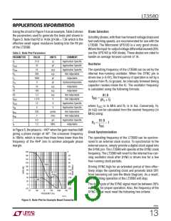
UsingthecircuitinFigure14asanexample, Table3shows
the parameters used to generate the bode plot shown in
Figure 5. Note that R2 is 14.6k ||14.6k = 7.3k which is the
effective small signal resistance looking into the FB pin
of the LT3580.
Diode Selection
Schottky diodes, with their low forward voltage drops and
fast switching speeds, are recommended for use with the
LT3580. The Microsemi UPS120 is a very good choice.
Wheretheinput-to-outputvoltagedifferentialexceeds20V,
use the UPS140 (a 40V diode). These diodes are rated to
handle an average forward current of 1A.
Table 3. Bode Plot Parameters
PARAMETER
VALUE
21.8
10
UNITS
Ω
COMMENT
Application Specific
Application Specific
Application Specific
Not Adjustable
Adjustable
R
L
Oscillator
C
μF
OUT
R
R
10
The operating frequency of the LT3580 can be set by the
internal free-running oscillator. When the SYNC pin is
driven low (< 0.4V), the frequency of operation is set by a
mΩ
kΩ
pF
ESR
O
305
1000
0
C
C
C
resistor from R to ground. An internally trimmed timing
T
pF
Optional/Adjustable
Adjustable
PL
capacitor resides inside the IC. The oscillator frequency
R
10
kΩ
kΩ
kΩ
V
C
is calculated using the following formula:
R1
R2
130
7.3
Adjustable
Not Adjustable
Not Adjustable
Application Specific
Application Specific
Not Adjustable
Not Adjustable
Application Specific
Adjustable
91.9
fOSC
=
V
V
V
1.215
12
REF
OUT
IN
(RT +1)
is in MHz and R is in kΩ. Conversely, R
T
V
where f
OSC
T
5
V
(in kΩ) can be calculated from the desired frequency (in
g
g
L
230
7
μmho
mho
μH
ma
MHz) using:
mp
4.2
1.2
91.9
fOSC
RT =
ꢀ1
f
MHz
S
In Figure 5, the phase is –140° when the gain reaches 0dB
giving a phase margin of 40°. The crossover frequency
is 10kHz, which is more than three times lower than the
frequency of the RHP zero to achieve adequate phase
margin.
Clock Synchronization
The operating frequency of the LT3580 can be synchro-
nized to an external clock source. To synchronize to the
external source, simply provide a digital clock signal into
the SYNC pin. The LT3580 will operate at the SYNC clock
frequency. The LT3580 will revert to the internal free-run-
ning oscillator clock after SYNC is driven low for a few
free-running clock periods.
180
160
140
120
0
–20
–40
–60
PHASE
100
80
–80
Driving SYNC high for an extended period of time effec-
tively stops the operating clock and prevents latch SR1
from becoming set (see the Block Diagram). As a result,
the switching operation of the LT3580 will stop.
–100
40° AT
60
40
–120
–140
–160
–180
–200
10kHz
GAIN
100
20
The duty cycle of the SYNC signal must be between 35%
and 65% for proper operation. Also, the frequency of the
SYNC signal must meet the following two criteria:
0
–20
10
1k
10k
100k
1M
FREQUENCY (Hz)
3580 F05
Figure 5. Bode Plot for Example Boost Converter
3580fc
13

 Linear [ Linear ]