LT3580
APPLICATIONS INFORMATION
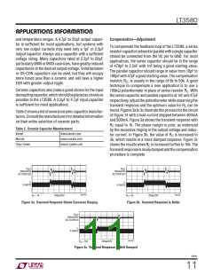
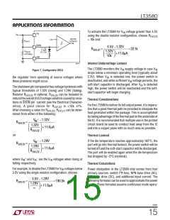
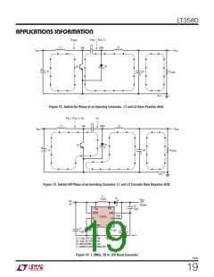
To activate the LT3580 for V voltage greater than 4.5V
IN
V
IN
V
IN
using the double resistor configuration, choose R
= 10k and:
UVLO2
ACTIVE/
LOCKOUT
1.3V
–
+
R
UVLO1
SHDN
4.5V ꢀ1.32V
RUVLO1
=
= 22.1k
11.6μA
AT 1.3V
R
1.32V
10k
ꢁ
ꢂ
ꢄ
ꢅ
UVLO2
(OPTIONAL)
+11.6μA
ꢃ
ꢆ
GND
3580 F07
Internal Undervoltage Lockout
The LT3580 monitors the V supply voltage in case V
IN
IN
Figure 7. Configurable UVLO
drops below a minimum operating level (typically about
2.3V). When V is detected low, the power switch is
the regulator from operating at source voltages where
these problems might occur.
IN
deactivated, and while sufficient V voltage persists, the
IN
soft-start capacitor is discharged. After V is detected
IN
Theshutdownpincomparatorhasvoltagehysteresiswith
typical thresholds of 1.32V (rising) and 1.29V (falling).
high, the power switch will be reactivated and the soft-
start capacitor will begin charging.
Resistor R
is optional. R
can be included to
UVLO2
UVLO2
reducetheoverallUVLOvoltagevariationcausedbyvaria-
Thermal Considerations
tions in SHDN pin current (see the Electrical Character-
FortheLT3580todeliveritsfulloutputpower, itisimpera-
tive that a good thermal path be provided to dissipate the
heat generated within the package. This is accomplished
bytakingadvantageofthethermalpadontheundersideof
the IC. It is recommended that multiple vias in the printed
circuit board be used to conduct heat away from the IC
and into a copper plane with as much area as possible.
istics). A good choice for R
UVLO2 UVLO1
mined from either of the following:
is ≤10k 1%.
can be deter-
UVLO2
, R
After choosing a value for R
+
V
ꢀ1.32V
IN
RUVLO1
=
=
ꢁ
ꢄ
1.32V
+11.6μA
ꢃ
ꢆ
R
ꢂ
UVLO2 ꢅ
or
Thermal Lockout
ꢀ
If the die temperature reaches approximately 165°C, the
part will go into thermal lockout, the power switch will be
turned off and the soft-start capacitor will be discharged.
The part will be enabled again when the die temperature
has dropped by ~5°C (nominal).
V
ꢀ1.29V
IN
RUVLO1
ꢁ
ꢄ
1.29V
+11.6μA
ꢃ
ꢆ
R
ꢂ
UVLO2 ꢅ
+
–
where V and V are the V voltages when rising or
IN
IN
IN
falling respectively.
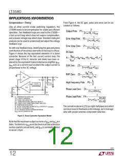
Thermal Calculations
For example, to disable the LT3580 for V voltages below
Power dissipation in the LT3580 chip comes from four
IN
2
3.5V using the single resistor configuration, choose:
primary sources: switch I R loss, NPN base drive (AC),
NPN base drive (DC), and additional input current. The
following formulas can be used to approximate the power
losses. These formulas assume continuous mode opera-
3.5V ꢀ1.29V
RUVLO1
=
=190.5k
1.29V
ꢂ
ꢃ
ꢅ
ꢇ
+11.6μA
ꢄ
ꢆ
ꢁ
3580fc
15

 Linear [ Linear ]