LT3580
APPLICATIONS INFORMATION
and temperature ranges. A 4.7μF to 20μF output capaci-
tor is sufficient for most applications, but systems with
very low output currents may need only a 1μF or 2.2μF
output capacitor. Always use a capacitor with a sufficient
voltage rating. Many capacitors rated at 2.2μF to 20μF,
par ticularly 0805 or 0603 case sizes, have greatly reduced
capacitance at the desired output voltage. Solid tantalum
or OS-CON capacitors can be used, but they will occupy
more board area than a ceramic and will have a higher
ESR with greater output ripple.
Compensation—Adjustment
To compensate the feedback loop of the LT3580, a series
resistor-capacitornetworkinparallelwithasinglecapacitor
should be connected from the VC pin to GND. For most
applications, the series capacitor should be in the range
of 470pF to 2.2nF with 1nF being a good starting value.
The parallel capacitor should range in value from 10pF to
100pF with 47pF a good starting value. The compensation
resistor, R , is usually in the range of 5k to 50k. A good
C
technique to compensate a new application is to use a
Ceramic capacitors also make a good choice for the input
decoupling capacitor, which should be placed as closely as
possible to the LT3580. A 2.2μF to 4.7μF input capacitor
is sufficient for most applications.
100kΩ potentiometer in place of series resistor R . With
C
the series capacitor and parallel capacitor at 1nF and 47pF
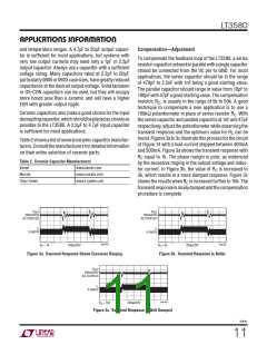
respectively, adjust the potentiometer while observing the
transient response and the optimum value for R can be
C
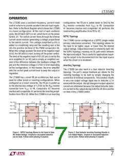
found.Figures3ato3cillustratethisprocessforthecircuit
of Figure 14 with a load current stepped between 400mA
and 500mA. Figure 3a shows the transient response with
Table2showsalistofseveralceramiccapacitormanufac-
turers.Consultthemanufacturersfordetailedinformation
on their entire selection of ceramic parts.
R equal to 1k. The phase margin is poor, as evidenced
C
Table 2. Ceramic Capacitor Manufacturers
by the excessive ringing in the output voltage and induc-
Kemet
www.kemet.com
www.murata.com
www.t-yuden.com
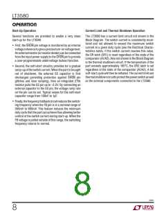
tor current. In Figure 3b, the value of R is increased to
C
Murata
3k, which results in a more damped response. Figure 3c
Taiyo Yuden
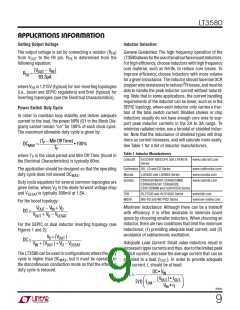
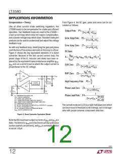
showstheresultswhenR isincreasedfurtherto10k. The
C
transientresponseisnicelydampedandthecompensation
procedure is complete.
V
V
OUT
OUT
200mV/DIV
200mV/DIV
AC COUPLED
AC COUPLED
I
I
L
L
0.5A/DIV
0.5A/DIV
3580 F03a
3580 F03b
R
C
= 1k
200μs/DIV
R
C
= 3k
200μs/DIV
Figure 3a. Transient Response Shows Excessive Ringing
Figure 3b. Transient Response Is Better
V
OUT
200mV/DIV
AC COUPLED
I
L
0.5A/DIV
3580 F03c
R
C
= 10k
200μs/DIV
Figure 3c. Transient Response Is Well Damped
3580fc
11

 Linear [ Linear ]