LT3587
APPLICATIONS INFORMATION
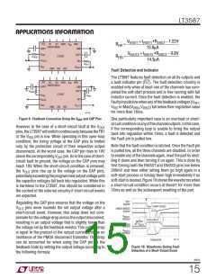
Besides acting as a fault output indicator, the Fault pin
is also an input pin. If this pin is externally forced low
below 400mV, the LT3587 behaves as if a fault event has
been detected and all the channels turn off. In order to
turn the part back on, remove the external voltage that
forces the pin low and reset the part. Figure 11 shows the
waveforms when the Fault pin is externally forced low and
the subsequent resetting of the part.
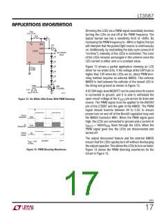
Since the programmed V
current is proportional to
OUT3
thecurrentthroughR , theLEDcurrentcanbeadjusted
IFB3
according to the following formula:
I
= (0.8V – V
) • 200/R
DAC-OUT IFB3
VOUT3
A higher DAC output voltage level results in lower LED
current and hence lower overall brightness. Conversely,
a lower DAC output voltage results in higher LED current
andhigherbrightness.NotethattheDACoutputimpedance
should be low enough to be able to sink approximately
1/200 of the desired maximum LED current without any
appreciable error for accurate dimming control.
V
FLT FORCED LOW
PART RESET
FLT
5V/DIV
ENSS1/ENSS3
5V/DIV
Note also that the maximum output current is limited by
the output disconnect current limit to 110mA (typ).
V
VOUT1
10V/DIV
V
NEG
10V/DIV
PWM Dimming
V
VOUT3
20V/DIV
Changing the forward current flowing in the LEDs not
only changes the brightness intensity of the LEDs, it also
changes the color. The chromaticity of the LEDs changes
with the change in forward current. Many applications
cannot tolerate any shift in the color of the LEDs. Control-
ling the intensity of the LEDs with a direct PWM signal
allows dimming of the LEDs without changing the color.
In addition, direct PWM dimming offers a wider dimming
range to the user.
3587 F11
100ms/DIV
Figure 11. Waveforms When the
Fault Pin is Externally Forced Low
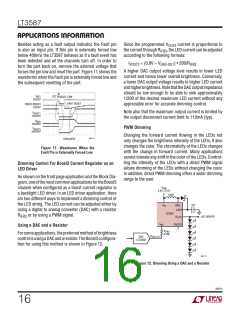
Dimming Control For Boost3 Current Regulator as an
LED Driver
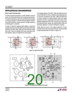
As shown on the front page application and the Block Dia-
gram,oneofthemostcommonapplicationsfortheBoost3
channel when configured as a boost current regulator is
a backlight LED driver. In an LED driver application, there
are two different ways to implement a dimming control of
the LED string. The LED current can be adjusted either by
using a digital to analog converter (DAC) with a resistor
V
VIN
2.5V TO 5V
10μH
1μF
V
SW3
IN
CAP3
LT3587
R
IFB3
or by using a PWM signal.
V
LED DRIVER
OUT3
I
EN/SS3
FB3
Using a DAC and a Resistor
R
IFB3
Forsomeapplications,thepreferredmethodofbrightness
controlisusingaDACandaresistor.TheBoost3configura-
tion for using this method is shown in Figure 12.
8.06k
V
DAC
LTC2630
DAC-OUT
3587 F12
Figure 12. Dimming Using a DAC and a Resistor
3587fc
16

 Linear [ Linear ]