LT3587
APPLICATIONS INFORMATION
100
1kHz
10
IDEAL
300Hz
1
0.1
MEASURED
100Hz
0.01
1
10
PWM DIMMING RANGE
100
1
10
DUTY CYCLE (%)
100
3587 F16
3587 F15
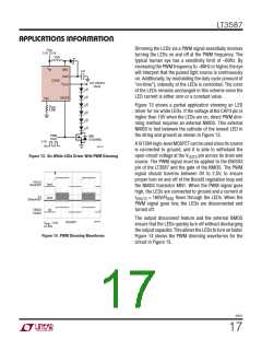
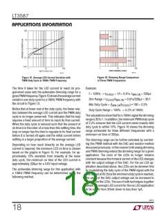
Figure 15. Average LED Current Variation with
PWM Duty Cycle at 100Hz PWM Frequency
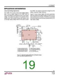
Figure 16. Dimming Range Comparison
of Three PWM Frequencies
The time it takes for the LED current to reach its pro-
grammed value sets the achievable dimming range for a
givenPWMfrequency.Figure15showstheaveragecurrent
variation over duty cycle for a 100Hz PWM frequency with
the circuit in Figure 13.
Example:
f = 100Hz → t
= 1/f = 0.01s, t
= 320μs
PERIOD
MIN-ON
Dim Range = t
/t
= 0.01s/320μs ≈ 30:1
PERIOD MIN-ON
Min Duty Cycle = (t
/t
) • 100 = 3.2%
MIN-ON PERIOD
Notice that at lower end of the duty cycle, the linear rela-
tion between the average LED current and the PWM duty
cycle is no longer preserved. This indicates that the loop
requires a fixed amount of time to reach its final current.
When the duty cycle is reduced such that the amount of
on time is in the order of or less than this settling time, the
loop no longer has the time to regulate to its final current
before it is turned off again and the initial current before
settling is a larger proportion of the average current.
Duty Cycle Range = 100% → 3.2% at 100Hz
Thecalculationsshowthatfora100Hzsignalthedimming
rangeis30to1. Inaddition, theminimumPWMdutycycle
of 3.2% ensures that the LED current varies linearly with
duty cycle to within 10%. Figure 16 shows the dimming
range achievable for three different frequencies with a
minimum on time of 320μs.
The dimming range can be further extended by combin-
ing this PWM method with the DAC and resistor method
discussedpreviously.Inthismannerbothanalogdimming
and PWM dimming extend the dimming range for a given
application. The color of the LEDs no longer remains
constant because the forward current of the LED changes
with the output voltage of the DAC. For the six LED ap-
plication described above, the LEDs can be dimmed first
by modulating the duty cycle of the PWM signal with the
DACoutputat0V.Oncetheminimumdutycycleisreached,
the value of the DAC output voltage can be increased to
further dim the LEDs. The use of both techniques together
allows the average LED current for the six LED application
to be varied from 20mA down to less than 1μA.
Depending on how much linearity on the average LED
current is required, the minimum LED on time is chosen
based on the graphs in Figure 15. For example, for ap-
proximately 10% deviation from linearity at the lower
duty cycle, the minimum on time of the LED current is
approximately 320μs for a 3.6V input voltage.
The achievable dimming range for this application with
a 100Hz PWM frequency can be determined using the
following method.
3587fc
18

 Linear [ Linear ]