LT3587
APPLICATIONS INFORMATION
Dimming the LEDs via a PWM signal essentially involves
turning the LEDs on and off at the PWM frequency. The
typical human eye has a sensitivity limit of ~60Hz. By
increasing the PWM frequency to ~80Hz or higher, the eye
will interpret that the pulsed light source is continuously
on. Additionally, by modulating the duty cycle (amount of
“on-time”), intensity of the LEDs is controlled. The color
of the LEDs remains unchanged in this scheme since the
LED current is either zero or a constant value.
V
VIN
2.5V TO 5V
10μH
V
IN
SW3
1μF
CAP3
LT3587
LED DRIVER
20mA
V
OUT3
I
EN/SS3
FB3
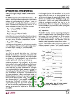
Figure 13 shows a partial application showing an LED
driver for six white LEDs. If the voltage at the CAP3 pin is
higher than 10V when the LEDs are on, direct PWM dim-
ming method requires an external NMOS. This external
NMOS is tied between the cathode of the lowest LED in
the string and ground as shown in Figure 13.
R
IFB3
8.06k
PWM
FREQ
MN1
Si1304BDL
2.5V
0V
A Si1304 logic-level MOSFET can be used since its source
is connected to ground, and it is able to withstand the
3587 F13
open-circuit voltage at the V
pin across its drain and
Figure 13. Six White LEDs Driver With PWM Dimming
OUT3
source. The PWM signal must be applied to the EN/SS3
pin of the LT3587 and the gate of the NMOS. The PWM
signal should traverse between 0V to 2.5V, to ensure
proper turn on and off of the Boost3 regulation loop and
the NMOS transistor MN1. When the PWM signal goes
high, the LEDs are connected to ground and a current of
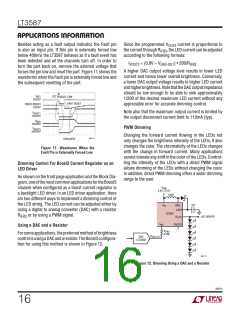
I
VOUT3
0mA
13mA/DIV
I
L4
0mA
0V
I
= 160V/R
flows through the LEDs. When the
VOUT3
IFB3
200mA/DIV
PWM signal goes low, the LEDs are disconnected and
turned off.
ENSS3
5V/DIV
The output disconnect feature and the external NMOS
ensure that the LEDs quickly turn off without discharging
theoutputcapacitor. ThisallowstheLEDstoturnonfaster.
Figure 14 shows the PWM dimming waveforms for the
circuit in Figure 13.
3587 F14
2ms/DIV
V
= 3.6V
VIN
6 LEDs
Figure 14. PWM Dimming Waveforms
3587fc
17

 Linear [ Linear ]