LT3587
APPLICATIONS INFORMATION
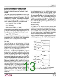
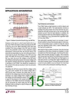
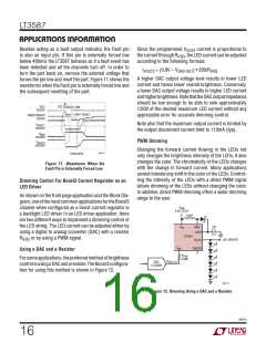
VVOUT1 +IVOUT1 •RDISC1 −1.22V
13.8μA
VVOUT3 +IVOUT3 •RDISC3 − 0.8V
14.3μA
FLT
B1
B3 SW3
V
IN
SW1
GND
RFB1
RFB3
=
=
EN/SSEN/SS
CAP3
V
CAP1
FB1
FB3
LT3587
R
VFB3
V
I
OUT3
R
FB1
V
FB3
OUT1
DN
SW2
FB2
Fault Detection and Indicator
The LT3587 features fault detection on all its outputs and
a fault indicator pin (FLT). The fault detection circuitry is
enabled only when at least one of the channels has com-
pleted the soft-start process and is free running with full
inductor current. Once the fault detection is enabled, the
FLT
B1
B3 SW3
V
IN
SW1
EN/SSEN/SS
CAP3
GND
CAP1
R
VFB3
LT3587
V
FB3
R
FB1
FB1
V
I
OUT3
Faultpinpullslowwhenanyofthefeedbackvoltages(V
,
FB1
V
FB3
OUT1
DN
SW2
FB2
V
or Max(V
,V )) fall below their regulation value
FB2
VFB3 IFB3
for more than 16ms.
3587 F09
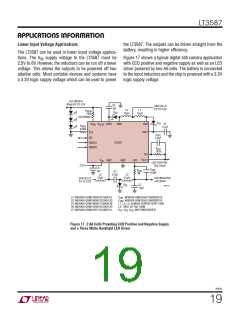
Figure 9. Feedback Connection Using the VOUT and CAP Pins
One particularly important case is an overload or short-
circuitconditiononanyofthechanneloutputs.Inthiscase,
if the corresponding loop is unable to bring the output
back into regulation within 16ms, a fault is detected and
the Fault pin is pulled low.
However, in the case of a short-circuit fault at the V
OUT
pins, the LT3587 will switch continuously because the FB1
or the V pin is low. While operating in this open-loop
FB3
condition, the rising voltage at the CAP pins is limited
only by the protection circuit of their respective output
disconnects. At the worst case, the CAP pin rises to 10V
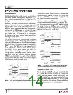
Note that the fault condition is latched. Once the Fault pin
is pulled low, all the three channels are disabled. In order
to enable any of the channels again, reset the part by shut-
ting it down and then turning it on again. This is done by
first forcing both the EN/SS1 and EN/SS3 pins low below
200mV and then either letting them go high again in a
soft-start process or forcing them high immediately if no
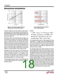
soft-startisdesired.Figure10showsthewaveformswhen
a short-circuit condition occurs at Boost1 for more than
16ms as well as the subsequent resetting of the part.
abovethecorrespondingV
pin. Sointhecaseofshort-
OUT
circuit fault to ground, the voltage on the CAP pins may
reach 10V. When the short-circuit condition is removed,
the V
pins rise up to the voltage on the CAP pins,
OUT
potentiallyexceedingtheprogrammedoutputvoltageuntil
the capacitor voltages fall back into regulation. While this
is harmless to the LT3587, this should be considered in
the context of the external circuitry if short-circuit events
are expected.
V
FLT
Regulating the CAP pins ensures that the voltage on the
OUT
5V/DIV
PART RESET
V
pins never exceeds the set output voltage after a
ENSS1/ENSS3
5V/DIV
short-circuit event. However, this setup does not com-
pensateforthevoltagedropacrosstheoutputdisconnect,
resulting in an output voltage that is slightly lower than
the voltage set by the feedback resistor. This voltage drop
is equal to the product of the output current and the on
resistance of the PMOS disconnect transistor. This drop
can be accounted for when using the CAP pin as the
feedback node by setting the output voltage according to
the following formula:
V
VOUT1
10V/DIV
SHORT
V
AT V
OUT1
NEG
10V/DIV
V
VOUT3
20V/DIV
3587 F10
100ms/DIV
Figure 10. Waveforms During Fault
Detection of a Short-Circuit Event
3587fc
15

 Linear [ Linear ]