LT3587
APPLICATIONS INFORMATION
Inductor Selection
Fortheinvertingchannel,theinrushcurrentflowsfromthe
input through inductor L2, charging the flying capacitor
A 15μH inductor and a 10μH inductor are recommended
for the LT3587 Boost1 channel and Boost3 channel re-
spectively. The inverting channel can use 15μH or 22μH
inductors. Although small size is the major concern for
mostapplications, forhighefficiencytheinductorsshould
have low core losses at 1MHz and low DCR (copper wire
resistance). The inductor DCR should be on the order of
half of the switch on resistance for its channel: 0.5ꢀ for
Boost1,0.4ꢀfortheinverterand1ꢀforBoost3.Forrobust
applications, the inductors should have current ratings
corresponding to their respective peak current during
regulation. Furthermore, with no soft-start, the inductor
should also be able to withstand temporary high start-up
currents of 1A, 1.1A and 480mA for the Boost1, inverter
and Boost3 channels respectively (typ, refer to the Typical
Performance Characteristics curves).
C2 and returning through the Schottky diode D .
S2
The selection of inductor and capacitor values should
ensure that the peak inrush current is below the rated
momentary maximum current of the Schottky diodes. The
peak inrush current can be estimated as follows:
−1
tan−1(ϕ)
(VVIN − 0.6)•e ϕ
IP =
L
C
4L
R2C
ϕ =
−1
where L is the inductance, C is the capacitance and R is
thetotalseriesresistanceintheinrushcurrentpath, which
includes the resistance of the inductor and the Schottky
diode. Note that in this equation, we model the Schottky
as having a fixed 0.6V drop.
Capacitor Selection
The small size of ceramic capacitors makes them suitable
for LT3587 applications. X5R and X7R types of ceramic
capacitors are recommended because they retain their
capacitance over wider voltage and temperature ranges
than other types such as Y5V or Z5U. A 1μF input ca-
pacitor is sufficient for most LT3587 applications. The
output capacitors required for stability depend on the
application. For most applications, the output capacitor
values required are: 10μF for the Boost1 channel, 22μF
for the inverter channel and 2.2μF for the Boost3 chan-
nel. The inverter requires a 2.2μF flying capacitor. Note
that this flying capacitor needs a voltage rating of at least
Table 1 gives inrush peak currents for some component
selections. Note that inrush current is not a concern if the
input voltage rises slowly.
Table 1. Inrush Peak Current
V
(V)
R (Ω)
0.68
L (μH)
15
C (μF)
10
I (A)
VIN
P
5
5
5
2.48
1.19
1.64
1.64
0.80
1.10
0.68
22
2.2
2.2
10
0.68
10
3.6
3.6
3.6
0.745
0.745
0.745
15
22
2.2
2.2
V + |V |.
IN
NEG
10
Inrush Current
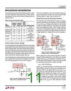
Schottky Diode Selection
For any of the external diode (D , D and D ) selec-
tions, besides having sufficiently high reverse breakdown
voltagetowithstandtheoutputvoltage, bothforwardvolt-
age drop and diode capacitance need to be considered.
Schottkydiodesratedforhighercurrentusuallyhavelower
forward voltage drops and larger capacitance. Although
lower forward voltage drop is good for efficiency, a large
When a supply voltage is abruptly applied to the V pin,
IN
S1 S2
S3
the voltage difference between the V pin and the CAP
IN
pins generates inrush current. For the case of the Boost1
channel, the inrush current flows from the input through
the inductor L1 and the Schottky D to charge the Boost1
S1
output capacitor C1. Similarly for the Boost3 channel, the
inrush current flows from the input through the inductor
L4andtheSchottkyD tochargetheoutputcapacitorC4.
S3
3587fc
10

 Linear [ Linear ]