LANSDALE Semiconductor, Inc.
ML1451xx
3. Assume the ÷N counter and the ÷A counter (with all the
higher order bits above “a” ignored) combined into a single
binary counter of n + a bits in length (n = number of divider
stages in the ÷N counter). The MSB of this “hypothetical”
counter is to correspond to the MSB of ÷ N and the LSB is to
correspond to the LSB of ÷ A. The system divide value, N ,
T
now results when the value of N in binary is used to program
T
the “new” n + a bit counter.
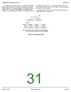
By using the two devices, several dual–modulus values are
achievable (shown in Figure 13).
MC
DEVICE A
DEVICE B
DEVICE
B
DEVICE A
MC10131
MC10138
ML12009
ML12011
ML12013
÷
÷
20/
÷
÷
21
51
÷
÷
32/
÷
33
÷
40/
÷
÷
41
50/
80/÷
81
÷
100/
101
NOTE: ML12009, ML12011, and ML12013 are pin equivalent.
ML12015, ML12016, and ML12017 are pin equivalent.
Figure 13. Dual–Modulus Values
Page 31 of 35
www.lansdale.com
Issue A

 LANSDALE [ LANSDALE SEMICONDUCTOR INC. ]