LANSDALE Semiconductor, Inc.
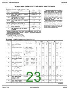
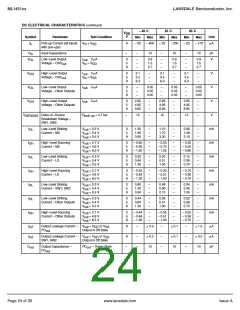
ML1451xx
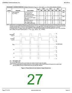
FREQUENCY CHARACTERISTICS (Voltages References to V , C = 50 pF, Input t = t =10 ns unless otherwise indicated)
SS
L
r
f
– 40 C
25 C
Max
85 C
Max
V
DD
V
Symbol
Parameter
Input Frequency
(f , OSC )
in in
Test Condition
Min
Max
Min
Min
Unit
f
i
R ≥ 8, A ≥ 0, N ≥ 8
= 500 mV p–p
AC coupled sine wave
3
5
9
–
–
–
6
15
15
–
–
–
6
15
15
–
–
–
6
15
15
MHz
MHz
MHz
V
in
R ≥ 8, A ≥ 0, N ≥ 8
= 1 V p–p AC coupled
sine wave
3
5
9
–
–
–
12
22
25
–
–
–
12
20
22
–
–
–
7
20
22
V
in
R ≥ 8, A ≥ 0, N ≥ 8
3
5
9
–
–
–
13
25
25
–
–
–
12
22
25
–
–
–
8
22
25
V
= V
to V
in
DC coupled square wave
DD SS
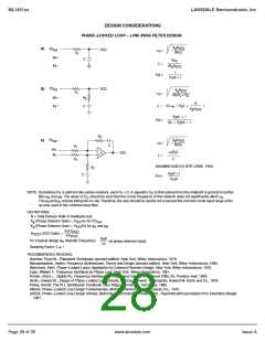
NOTE: Usually, the PLL's propagation delay from f to MC plus the setup time of the prescaler determines the upper frequency limit of the system.
in
The upper frequency limit is found with the following formula:f = P /(t + t ) where f is the upper frequency in Hz, P is the lower of the dual
P
set
modulus prescaler ratios, t is the f to MC propagation delay in seconds, and t is the prescaler setup time in seconds.
set
P
in
For example, with a 5 V supply, the f to MC delay is 70 ns. If the MC12028A prescaler is used, the setup time is 16 ns. Thus, if the 64/65
in
ratio is utilized, the upper frequency limit is f = P/(t + t ) = 64/(70 + 16) = 744 MHz.
set
P
f
V
R
H
REFERENCE
OSC
÷
R
V
V
L
f
H
V
FEEDBACK
(f N)
÷
V
V
in
L
H
*
HIGH IMPEDANCE
PD
out
V
V
L
H
φ
R
V
V
L
H
φ
V
V
V
L
H
LD
V
L
V
H
V
L
= High Voltage Level.
= Low Voltage Level.
* At this point, when both f and f are in phase, the output is forced to near mid–supply.
R
V
NOTE: The PD
generates error pulses during out–of–lock conditions.When locked in phase and frequency the output is high
and the voltage at this pin is determined by the low–pass filter capacitor.
out
Figure 9. Phase Detector/Lock Detector Output Waveforms
Page 27 of 35
www.lansdale.com
Issue A

 LANSDALE [ LANSDALE SEMICONDUCTOR INC. ]