ML1451xx
LANSDALE Semiconductor, Inc.
Table 1. Partial List of Crystal Manufacturers
United States Crystal Corp.
Crystek Crystal
Statek Corp.
Fox Electronics
NOTE: Lansdale and Motorola do not recommend one supplier over another and in no
way suggests that this is a complete listing of crystal manufacturers.
RECOMMENDED READING
DESIGN GUIDELINES
Technical Note TN–24, Statek Corp.
Technical Note TN–7, Statek Corp.
E. Hafner, “The Piezoelectric Crystal Unit – Definitions and
Method of Measurement”, Proc. IEEE, Vol. 57, No. 2
Feb.,1969.
D. Kemper, L. Rosine, “Quartz Crystals for
FrequencyControl”, Electro–Technology, June, 1969.
P. J. Ottowitz, “A Guide to Crystal Selection”, Electronic
Design, May, 1966.
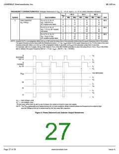
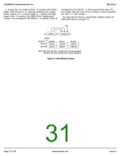
The system total divide value, N total (N ) will be dictated
T
by the application:
N is the number programmed into the ÷ N counter, A is the
frequency into the prescaler
N
=
= N • P + A
T
frequency into the phase detector
number programmed into the ÷ A counter, P and P + 1 are the
two selectable divide ratios available in the dual–modulus
prescalers. To have a range of N values in sequence, the
T
DUAL–MODULUS PRESCALING
OVERVIEW
÷ A counter is programmed from zero through P – 1 for a par-
ticular value N in the ÷ N counter. N is then incremented to N
+ 1 and the ÷ A is sequenced from 0 through P – 1 again.
There are minimum and maximum values that can be
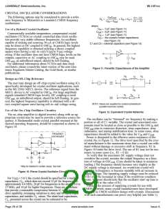
The technique of dual–modulus prescaling is well estab-
lished as a method of achieving high performance frequency
synthesizer operation at high frequencies. Basically, the
approach allows relatively low–frequency programmable coun-
ters to be used as high–frequency programmable counters with
speed capability of several hundred MHz. This is possible with
out the sacrifice in system resolution and performance that
results if a fixed (single–modulus) divider is used for the
prescaler.
In dual–modulus prescaling, the lower speed counters must
be uniquely configured. Special control logic is necessary to
select the divide value P or P + 1 in the prescaler for the
required amount of time (see modulus control definition).
Lansdale's dual–modulus frequency synthesizers contain this
feature and can be used with a variety of dual–modulus-
prescalers to allow speed, complexity and cost to be tailored to
the system requirements. Prescalers having P, P + 1 divide val-
ues in the range of ÷ 3/÷4 to ÷128/÷ 129 can be controlled by
most Lansdale frequency synthesizers.
achieved for N . These values are a function of P and the size
T
of the ÷ N and ÷ A counters.
The constraint N ≥ A always applies. If A
= P – 1, then
≥ P – 1. Then N min = (P – 1) P + A or (P – 1) P since
max
N
min
T
A is free to assume the value of 0.
NT = N
max max
• P + A
max
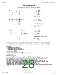
To maximize system frequency capability, the dual–modulus
prescaler output must go from low to high after each group of
P or P + 1 input cycles. The prescaler should divide by P when
its modulus control line is high and by P + 1 when its MC is
low.
For the maximum frequency into the prescaler (f
value used for P must be large enough such that:
), the
VCOmax
1.f
max divided by P may not exceed the frequency
divided by P must be greater than the
VCO
capability of f (input to the ÷ N and ÷ A counters).
2.The period of f
sum of the times:
in
VCO
Several dual–modulus prescaler approaches suitable for use
with the MC145152 (Motorola), ML145156, or ML145158 are:
a. Propagation delay through the dual–modulus prescaler.
b. Prescaler setup or release time relative to its MC signal.
c. Propagation time from f to the MC output for the
frequency synthesizer device.
A sometimes useful simplification in the programming code
can be achieved by choosing the values for P of 8, 16, 32, or
in
ML12009
ML12011
ML12013
ML12015
ML12016
ML12017
ML12018
MC12028A
MC12034
MC12038
ML12052
ML12054A
÷5/÷6
÷8/÷9
440 MHz
500 MHz
500 MHz
225 MHz
225 MHz
225 MHz
520 MHz
1.1 GHz
2.0 GHz
1.1 GHz
1.1 GHz
2.0 GHz
÷10/÷11
÷32/÷33
64. For these cases, the desired value of N results when N
T
T
÷40/÷41
in binary is used as the program code to the ÷ N and ÷ A coun-
ters treated in the following manner:
÷64/÷65
÷128/÷129
÷32/33 or ÷64/65
÷32/33 or ÷64/65
÷127/128 or ÷255/256
÷64/65 or ÷128/129
÷64/65 or ÷128/129
a
1.Assume the ÷A counter contains “a” bits where 2 ≥P.
2.Always program all higher order ÷A counter bits above
“a” to 0.
Page 30 of 35
www.lansdale.com
Issue A

 LANSDALE [ LANSDALE SEMICONDUCTOR INC. ]