ISL6753
by the leading edge blanking (LEB) interval. The effective
Soft-Start Operation
delay is the sum of the two delays and is nominally 105nS.
The ISL6753 features a soft-start using an external capacitor
in conjunction with an internal current source. Soft-start
reduces component stresses and surge currents during start
up.
Voltage Feed Forward Operation
Voltage feed forward is a technique used to regulate the
output voltage for changes in input voltage without the
intervention of the control loop. Voltage feed forward is often
implemented in voltage-mode control loops, but is redundant
and unnecessary in peak current-mode control loops.
Upon start up, the soft-start circuitry limits the error voltage
input (VERR) to a value equal to the soft-start voltage. The
output pulse width increases as the soft-start capacitor
voltage increases. This has the effect of increasing the duty
cycle from zero to the regulation pulse width during the soft-
start period. When the soft-start voltage exceeds the error
voltage, soft-start is completed. Soft-start occurs during
start-up and after recovery from a fault condition. The soft-
start charging period may be calculated as follows:
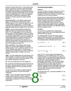
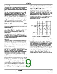
Voltage feed forward operates by modulating the sawtooth
ramp in direct proportion to the input voltage. Figure 5
demonstrates the concept.
VIN
(EQ. 6)
t = 64.3 ⋅ C
mS
ERROR VOLTAGE
RAMP
where t is the charging period in mS and C is the value of the
soft-start capacitor in µF.
CT
The soft-start voltage is clamped to 4.50V with a tolerance of
2%. It is suitable for use as a “soft-started” reference
provided the current draw is kept well below the 70µA
charging current.
OUTLL, LR
The outputs may be inhibited by using the SS pin as a
disable input. Pulling SS below 0.25V forces all outputs low.
An open collector/drain configuration may be used to couple
the disable signal into the SS pin.
FIGURE 5. VOLTAGE FEED FORWARD BEHAVIOR
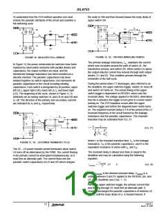
Input voltage feed forward may be implemented using the
RAMP input. An RC network connected between the input
voltage and ground, as shown in Figure 7, generates a
voltage ramp whose charging rate varies with the amplitude
of the source voltage. At the termination of the active output
pulse RAMP is discharged to ground so that a repetitive
sawtooth waveform is created. The RAMP waveform is
compared to the VERR voltage to determine duty cycle. The
selection of the RC components depends upon the desired
input voltage operating range and the frequency of the
oscillator. In typical applications the RC components are
selected so that the ramp amplitude reaches 1.0V at
minimum input voltage within the duration of one half-cycle.
Gate Drive
The ISL6753 outputs are capable of sourcing and sinking
10mA (at rated VOH, VOL) and are intended to be used in
conjunction with integrated FET drivers or discrete bipolar
totem pole drivers. The typical on resistance of the outputs is
50Ω.
Overcurrent Operation
The cycle-by-cycle peak current limit results in pulse-by-
pulse duty cycle reduction when the current feedback signal
exceeds 1.0V. When the peak current exceeds the
threshold, the active output pulse is immediately terminated.
This results in a decrease in output voltage as the load
current increases beyond the current limit threshold. The
ISL6753 operates continuously in an overcurrent condition
without shutdown.
If voltage-mode control is used in a bridge topology, it should
be noted that peak current limit results in inherently unstable
operation. The DC blocking capacitors used in voltage-mode
bridge topologies become unbalanced, as does the flux in
the transformer core. A latching overcurrent shutdown
method using external components is recommended.
The propagation delay from CS exceeding the current limit
threshold to the termination of the output pulse is increased
FN9182.1
9
March 10, 2005

 INTERSIL [ Intersil ]