ISL6753
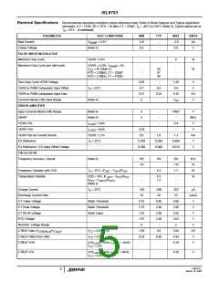
Electrical Specifications Recommended operating conditions unless otherwise noted. Refer to Block Diagram and Typical Application
schematic. 9 V < VDD< 20 V, RTD = 10.0kΩ, CT = 470pF, T = -40°C to 105°C (Note 3), Typical values are at
A
T
= 25°C (Continued)
A
PARAMETER
TEST CONDITIONS
MIN
TYP
MAX
UNITS
SOFT-START
Charging Current
SS Clamp Voltage
SS = 3V
-60
4.410
10
-70
4.500
-
-80
4.590
-
µA
V
SS Discharge Current
Reset Threshold Voltage
OUTPUTS
SS = 2V
= 25°C
mA
V
T
0.23
0.27
0.33
A
High Level Output Voltage (VOH)
Low Level Output Voltage (VOL)
Rise Time
I
I
= -10mA, VDD - VOH
-
-
-
-
-
0.5
0.5
110
90
-
1.0
1.0
V
V
OUT
OUT
= 10mA, VOL - GND
C
= 220pF, VDD = 15V(Note 4)
= 220pF, VDD = 15V(Note 4)
200
150
1.25
ns
ns
V
OUT
OUT
Fall Time
C
UVLO Output Voltage Clamp
THERMAL PROTECTION
Thermal Shutdown
VDD = 7V, I
= 1mA (Note 6)
LOAD
(Note 4)
(Note 4)
(Note 4)
130
115
-
140
125
15
150
135
-
°C
°C
°C
Thermal Shutdown Clear
Hysteresis, Internal Protection
NOTE:
3. Specifications at -40°C and 105°C are guaranteed by 25°C test with margin limits.
4. Guaranteed by design, not 100% tested in production.
5. This is the maximum duty cycle achievable using the specified values of RTD and CT. Larger or smaller maximum duty cycles may be obtained
using other values for these components. See Equations 1 - 5.
6. Adjust VDD below the UVLO stop threshold prior to setting at 7V.
FN9182.1
6
March 10, 2005

 INTERSIL [ Intersil ]