ISL6753
RESDEL is set properly, switch LL will be turned on at this
time.
and LR until the body diode of LR is forward biased. If
RESDEL is set properly, switch LR will be turned on at this
time.
VIN+
UL
UR
VIN+
IS
D1
UL
UR
IS
D1
VOUT+
RTN
LL
VOUT+
RTN
LL
IP
IP
LL
LR
LL
LR
D2
D2
VIN-
VIN-
FIGURE 13. UPPER SWITCH TOGGLE AND RESONANT
TRANSITION
FIGURE 16. UPPER SWITCH TOGGLE AND RESONANT
TRANSITION
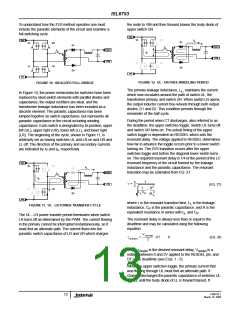
The second power transfer period commences when switch
LL closes. With switches UR and LL on, the primary and
secondary currents flow as indicated below.
The first power transfer period commences when switch LR
closes and the cycle repeats. The ZVS transition requires
that the leakage inductance has sufficient energy stored to
fully charge the parasitic capacitances. Since the energy
VIN+
2
UL
LL
UR
LR
stored is proportional to the square of the current (1/2 L I
,
L P
D1
D2
the ZVS resonant transition is load dependent. If the leakage
inductance is not able to store sufficient energy for ZVS, a
discrete inductor may be added in series with the
transformer primary.
VOUT+
RTN
LL
Fault Conditions
A fault condition occurs if VREF or VDD fall below their
undervoltage lockout (UVLO) thresholds or if the thermal
protection is triggered. When a fault is detected, the soft-
start capacitor is quickly discharged, and the outputs are
disabled low. When the fault condition clears and the soft-
start voltage is below the reset threshold, a soft-start cycle
begins.
VIN-
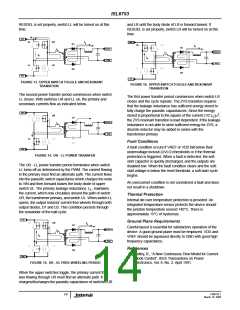
FIGURE 14. UR - LL POWER TRANSFER
The UR - LL power transfer period terminates when switch
LL turns off as determined by the PWM. The current flowing
in the primary must find an alternate path. The current flows
into the parasitic switch capacitance which charges the node
to VIN and then forward biases the body diode of upper
An overcurrent condition is not considered a fault and does
not result in a shutdown.
switch UL. The primary leakage inductance, L , maintains
L
the current, which now circulates around the path of switch
UR, the transformer primary, and switch UL. When switch LL
opens, the output inductor current free-wheels through both
output diodes, D1 and D2. This condition persists through
the remainder of the half-cycle.
Thermal Protection
Internal die over temperature protection is provided. An
integrated temperature sensor protects the device should
the junction temperature exceed 140°C. There is
approximately 15°C of hysteresis.
VIN+
Ground Plane Requirements
UL
UR
IS
D1
Careful layout is essential for satisfactory operation of the
device. A good ground plane must be employed. VDD and
VREF should be bypassed directly to GND with good high
frequency capacitance.
VOUT+
RTN
LL
IP
LL
LR
References
D2
[1] Ridley, R., “A New Continuous-Time Model for Current
Mode Control”, IEEE Transactions on Power
Electronics, Vol. 6, No. 2, April 1991.
VIN-
FIGURE 15. UR - UL FREE-WHEELING PERIOD
When the upper switches toggle, the primary current that
was flowing through UR must find an alternate path. It
charges/discharges the parasitic capacitance of switches UR
FN9182.1
14
March 10, 2005

 INTERSIL [ Intersil ]