ISL6366
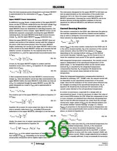
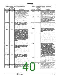
Package Outline Drawing
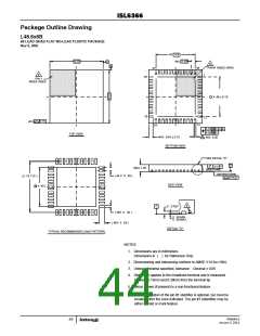
L48.6x6B
48 LEAD QUAD FLAT NO-LEAD PLASTIC PACKAGE
Rev 0, 9/09
4X
4.4
6.00
0.40
44X
A
6
B
PIN #1 INDEX AREA
48
37
6
1
36
PIN 1
INDEX AREA
4 .40 ± 0.15
25
12
0.15
(4X)
13
24
0.10 M C A B
0.05 M C
TOP VIEW
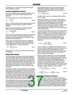
48X 0.45 ± 0.10
BOTTOM VIEW
4
48X 0.20
SEE DETAIL "X"
C
0.10
C
MAX 1.00
BASE PLANE
SEATING PLANE
0.08
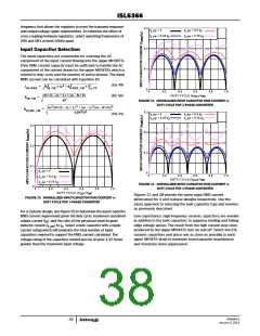
( 44 X 0 . 40 )
( 5. 75 TYP )
(
C
SIDE VIEW
4. 40 )
5
0 . 2 REF
C
( 48X 0 . 20 )
0 . 00 MIN.
0 . 05 MAX.
( 48X 0 . 65 )
DETAIL "X"
TYPICAL RECOMMENDED LAND PATTERN
NOTES:
1. Dimensions are in millimeters.
Dimensions in ( ) for Reference Only.
2. Dimensioning and tolerancing conform to AMSE Y14.5m-1994.
3.
Unless otherwise specified, tolerance : Decimal ± 0.05
4. Dimension applies to the metallized terminal and is measured
between 0.15mm and 0.30mm from the terminal tip.
Tiebar shown (if present) is a non-functional feature.
5.
The configuration of the pin #1 identifier is optional, but must be
located within the zone indicated. The pin #1 indentifier may be
either a mold or mark feature.
6.
FN6964.0
January 3, 2011
44

 INTERSIL [ Intersil ]