HSP50110
processing elements so that they are enabled once for each
6.5%. For real inputs, the magnitude detector reduces to a
an absolute value detector with negligible error.
time ENI is sampled low. This mode minimizes the
processing pipeline latency, and the latency of the part’s
serial interfaces while conserving power. Note: the
effective input sample rate to the internal processing
elements is equal to the frequency with which ENI is
asserted “low”.
Note: an external AGC loop using the Input Level
Detector may go unstable for a real sine wave input
whose frequency is exactly one quarter of the sample
rate (F /4). The Level Detector responds to such an
S
input by producing a square wave output with a 50%
duty cycle for a wide range of thresholds. This square
wave integrates to zero, indicating no error for a range
of input signal amplitudes.
In Interpolated Input Mode, the ENI input is used to insert
zeroes between the input data samples. This process
increases the input sample rate to the processing elements
which improves the time resolution of the processing chain.
When ENI is sampled “high” by CLK, a zero is input into the
processing pipeline. When ENI is sampled “low” the input
data is fed into the pipeline. Note: Due to the nature of the
rate change operation, consideration must be given to
the scaling and interpolation filtering required for a
particular rate change factor.
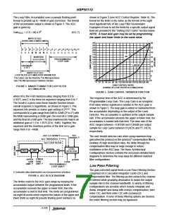
Synthesizer/Mixer
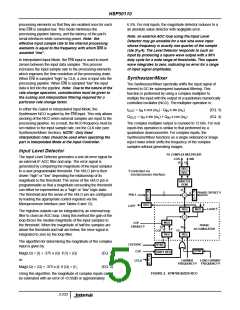
The Synthesizer/Mixer spectrally shifts the input signal of
interest to DC for subsequent baseband filtering. This
function is performed by using a complex multiplier to
multiply the input with the output of a quadrature numerically
controlled oscillator (NCO). The multiplier operation is:
In either the Gated or Interpolated Input Mode, the
I
= I x cos (ω ) - Q x sin (ω )
(EQ. 3)
(EQ. 4)
OUT
IN
c
IN
c
Synthesizer NCO is gated by the ENI input. This only allows
clocking of the NCO when external samples are input to the
processing pipeline. As a result, the NCO frequency must be
set relative to the input sample rate, not the CLK rate (see
Synthesizer/Mixer Section). NOTE: Only fixed
Q
= I x sin (ω ) + Q x cos (ω )
IN c IN c
OUT
The complex multiplier output is rounded to 12 bits. For real
inputs this operation is similar to that performed by a
quadrature downconverter. For complex inputs, the
Synthesizer/Mixer functions as a single-sideband or image
reject mixer which shifts the frequency of the complex
samples without generating images.
interpolation rates should be used when operating the
part in Interpolated Mode at the Input Controller.
Input Level Detector
TO COMPLEX MULTIPLIER
The Input Level Detector generates a one-bit error signal for
an external IF AGC filter and amp. The error signal is
generated by comparing the magnitude of the input samples
to a user programmable threshold. The HI/LO pin is then
driven “high” or “low” depending the relationship of its
magnitude to the threshold. The sense of the HI/LO pin is
programmable so that a magnitude exceeding the threshold
can either be represented as a “high” or “low” logic state.
The threshold and the sense of the HI/LO pin are configured
by loading the appropriate control registers via the
COS
10 10
SIN
REG
REG
†Controlled via
microprocessor interface.
SIN/COS
ROM
11
R
R
E
G
PHASE OFFSET †
2
8
PH0-1
+
E
G
Microprocessor Interface (see Tables 8 and 12).
REG
0
LOTP
LOAD †
REG
+
MUX
The high/low outputs can be integrated by an external loop
filter to close an AGC loop. Using this method the gain of the
loop forces the median magnitude of the input samples to
the threshold. When the magnitude of half the samples are
above the threshold and half are below, the error signal is
integrated to zero by the loop filter.
MUX
COF
ENABLE †
PHASE
ACCUMULATOR
32
32
COF
0
CF
REG
REG
The algorithm for determining the magnitude of the complex
input is given by:
COFSYNC
COF
SYNC
SHIFT REG
SYNC
Mag(I,Q) = |I| + .375 x |Q| if |I| > |Q|
or:
(EQ. 1)
R
E
G
CARRIER
LOAD CARRIER
CFLD
FREQUENCY† FREQUENCY†
Mag(I,Q) = |Q| + .375 x |I| if |Q| > |I|,
(EQ. 2)
FIGURE 2. SYNTHESIZER NCO
Using this algorithm, the magnitude of complex inputs can
be estimated with an error of <0.55dB or approximately
3-233

 INTERSIL [ Intersil ]