BBT3821
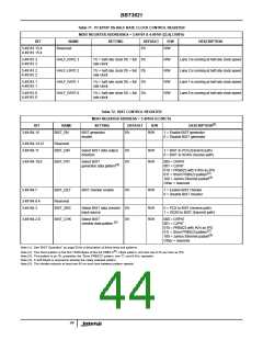
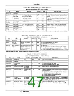
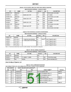
Table 78. IEEE 10GBASE-X PHY XGXS STATUS REGISTER
MDIO REGISTER ADDRESSES = 4.24 (4.0018’h)
BIT
4.24.15:13
4.24.12
NAME
Reserved
SETTING
DEFAULT
R/W
DESCRIPTION
(1)
PHY XS
Lane_Align
1 = 4 Lanes Aligned
0 = Lanes not aligned
1’b
RO
1 = Four 3G receive lanes (on egress path) are
aligned
4.24.11
Test_Pattern
Test Pattern Abilities
1’b
1’b
RO
RO
1 = The device is able to generate test patterns for
10GBASE-X
4.24.10
4.24.9:4
4.24.3
4.24.2
4.24.1
4.24.0
PHYXSLpbk
Reserved
Loopback Ability
1 = Device is able to loopback
(1)
(1)
(1)
(1)
Lane3 Sync
Lane2 Sync
Lane1 Sync
Lane0 Sync
1 = Lane is Synchronized
0 = Lane not Synchronized
1’b
1’b
1’b
1’b
RO
RO
RO
RO
Reflects the PCS_SYNC byte alignment state
machine condition; not valid if not enabled in
device (see Table 80)
Note (1): The status of these bits depends on the signal conditions. Default shown is for normal operation. The bits contribute to the RX Local Fault bit, see Table 77.
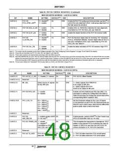
Table 79. IEEE 10GBASE-X PHY XGXS TEST CONTROL REGISTER
MDIO REGISTER ADDRESS = 4.25 (4.0019’h)
BIT
4.25.15:3
4.25.2
NAME
Reserved
SETTING
DEFAULT
R/W
DESCRIPTION
PHY XS
TestPatEn
Receive Test Pattern
Enable
0’b
R/W
R/W
0 = Do not enable Receive test pattern
1 = Enable Receive test pattern
4.25.1:0
PHY XS TestPat Test pattern select (see 00’b
Type
11 = Reserved
Table 72 for other test
patterns generated by
the BBT3821)
10 = Mixed frequency test pattern (Continuous /K/ = K28.5)
01 = Low frequency test pattern (repeat 0000011111 = K28.7)
00 = High frequency test pattern (repeat 0101010101 = D10.2)
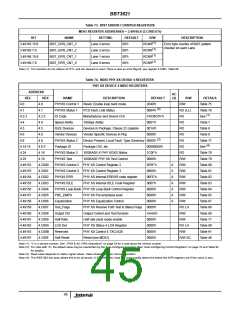
VENDOR-SPECIFIC PHY XS REGISTERS (4.C000’H TO 4.C00B’H)
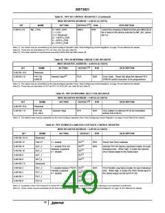
Table 80. PHY XS CONTROL REGISTER 2
MDIO REGISTER ADDRESS = 4.49152 (4.C000’h)
(1)
BIT
NAME
Test Mode
SETTING
DEFAULT
R/W
R/W
DESCRIPTION
4.49152.15:14
4.49152.13:12
4.49152.11
00’b
00’b
User should leave at 00’b
Reserved
PHY XS Clock
PSYNC
1’b
1’b
R/W
R/W
R/W
1 = Synchronize/align four lanes
0 = Do not synchronize/align four lanes
4.49152.10
4.49152.9:8
PHY XS CODECENA 0 = disable
1 = enable
Internal 8B/10B Codec enable/disable
PHY XS CDET[1:0]
Comma Detect 11’b
These bits individually enable positive and negative disparity
“comma” detection.
Select.
11 = Enable both positive and negative comma detection
10 = Enable positive comma detection only
01 = Enable negative comma detection only
00 = Disable comma detection
(2)
(3)
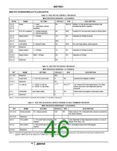
4.49152.7
PHY XS
0 = disable
1 = enable
0’b
R/W
R/W
Enable De-skew state machine control
. Forced enabled
DSKW_SM_EN
by PHY XS XAUI_EN. May not operate correctly unless the
PHY XS PCS_SYNC_EN bit is also set.
4.49152.6:5
PHY XS RCLKMODE 11’b = Local
Reference
11’b
Other values should only be used if incoming data is
(4)
frequency-synchronous with the local reference clock
.
(4)
Clock
47

 INTERSIL [ Intersil ]