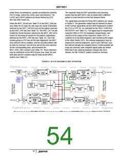
BBT3821
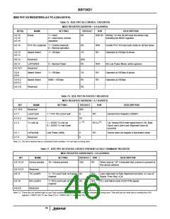
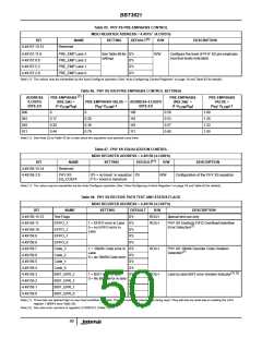
Table 85. PHY XS PRE-EMPHASIS CONTROL
MDIO REGISTER ADDRESS = 4.49157 (4.C005’h)
(1)
BIT
NAME
SETTING
DEFAULT
R/W
DESCRIPTION
4.49157.15:12
Reserved
4.49157.11:9
4.49157.8:6
4.49157.5:3
4.49157.2:0
PRE_EMP Lane 3
PRE_EMP Lane 2
PRE_EMP Lane 1
PRE_EMP Lane 0
SeeTable 86for 0’h
R/W
Configure the level of PHY XS pre-emphasis
(nominal levels indicated)
settings
0’h
0’h
0’h
Note (1): The values may be overwritten by the Auto-Configure operation (See “Auto-Configuring Control Registers” on page 16 and Table 92 for details).
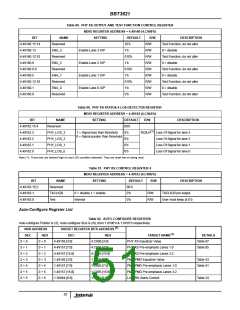
Table 86. PHY XS XAUI PRE-EMPHASIS CONTROL SETTINGS
(1)
ADDRESS
4.C005’h
BITS 2:0
PRE-EMPHASIS
(802.3ak) =
PRE-EMPHASIS
(802.3ak) =
PRE-EMPHASIS
VALUE =
PRE-EMPHASIS VALUE = ADDRESS 4.C005’h
(V / V )-1 BITS 2:0
(1-V
/V
)
(1-V
/V
)
(V / V
)-1
LOW HI
HI LOW
LOW HI
HI LOW
000
0
0
100
101
110
111
0.50
0.53
0.57
0.60
1.00
1.28
1.33
1.50
001
010
011
0.17
0.28
0.44
0.20
0.39
0.79
Note (1): See Note (2) to Table 42 for a note about the equations and symbols used here.
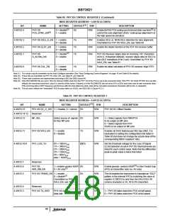
Table 87. PHY XS EQUALIZATION CONTROL
MDIO REGISTER ADDRESS = 4.49158 (4.C006’h)
(1)
BIT
4.49158.15:14
4.49158.3:0
NAME
Reserved
SETTING
DEFAULT
R/W
DESCRIPTION
PHY XS
EQ_COEFF
0’h = no boost in equalizer. 0’h
F’h = boost is maximum
R/W
Configuration of the PHY XS equalizer
Note (1): The value may be overwritten by the Auto-Configure operation (See “Auto-Configuring Control Registers” on page 16 and Table 92 for details).
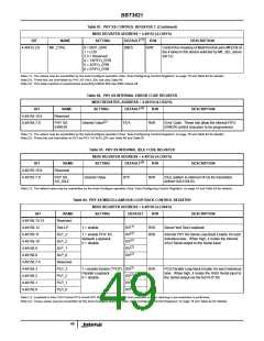
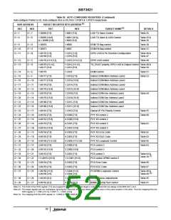
Table 88. PHY XS RECEIVE PATH TEST AND STATUS FLAGS
MDIO REGISTER ADDRESS = 4.49159 (4.C007’h)
BIT
4.49159.15:12
4.49159.11
4.49159.10
4.49159.9
4.49159.8
4.49159.7
4.49159.6
4.49159.5
4.49159.4
4.49159.3
4.49159.2
4.49159.1
4.49159.0
NAME
Test Flags
SETTING
DEFAULT
0’h
R/W
ROLH
ROLH
DESCRIPTION
Special test use only
EFIFO_3
1 = EFIFO error in Lane 0’b
0 = no EFIFO error in
PHY XS Elasticity FIFO Overflow/Underflow
(1)
Error Detection
EFIFO_2
0’b
Lane
EFIFO_1
0’b
0’b
EFIFO_0
Code_3
1 = 10b/8b Code error in 0’b
ROLH
ROLH
PHY XS 10b/8b Decoder Code Violation
(1)
Lane
Detection
Code_2
0’b
0 = no 10b/8b Code error
Code_1
0’b
0’b
Code_0
(1) (2)
BIST_ERR_3
BIST_ERR_2
BIST_ERR_1
BIST_ERR_0
1 = BIST error in lane
0 = No BIST error in lane
0’b
0’b
0’b
0’b
Lane by lane BIST error checker indicator
Note (1): These bits are latched high on any Fault condition detected. They are reset low (cleared) on being read. They will also be reset low on reading the LASI
register 1.9004’h (see Table 28)
Note (2): See also error counters in registers 3.C00D:E’h (Table 73)
50

 INTERSIL [ Intersil ]