82C59A
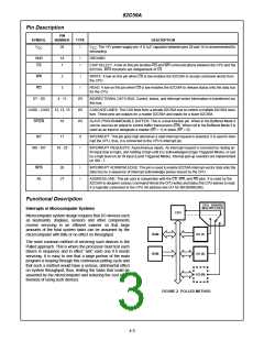
Initialization Command Words (lCWs)
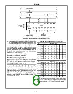
CONTENT OF THIRD INTERRUPT VECTOR BYTE
D7
D6
D5
D4
D3
D2
D1
D0
General
A15
A14
A13
A12
A11
A10
A9
A8
Whenever a command is issued with A0 = 0 and D4 = 1, this
is interpreted as Initialization Command Word 1 (lCW1).
lCW1 starts the initialization sequence during which the fol-
lowing automatically occur:
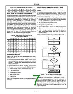
80C86, 8OC88, 80C286 Interrupt Response Mode
80C86/88/286 mode is similar to 8080/85 mode except that
only two Interrupt Acknowledge cycles are issued by the pro-
cessor and no CALL opcode is sent to the processor. The a. The edge sense circuit is reset, which means that follow-
first interrupt acknowledge cycle is similar to that of 8080/85
systems in that the 82C59A uses it to internally freeze the
state of the interrupts for priority resolution and, as a master,
it issues the interrupt code on the cascade lines. On this first
cycle, it does not issue any data to the processor and leaves
its data bus buffers disabled. On the second interrupt
acknowledge cycle in the 86/88/286 mode, the master (or
slave if so programmed) will send a byte of data to the pro-
cessor with the acknowledged interrupt code composed as
follows (note the state of the ADI mode control is ignored
and A5 - A11 are unused in the 86/88/286 mode).
ing initialization, an interrupt request (IR) input must make
a low-to-high transition to generate an interrupt.
b. The Interrupt Mask Register is cleared.
c. lR7 input is assigned priority 7.
d. Special Mask Mode is cleared and Status Read is set to
lRR.
e. If lC4 = 0, then all functions selected in lCW4 are set to
zero. (Non-Buffered mode (see note), no Auto-EOI,
8080/85 system).
NOTE: Master/Slave in ICW4 is only used in the buffered mode.
CONTENT OF INTERRUPT VECTOR BYTE FOR
80C86/88/286 SYSTEM MODE
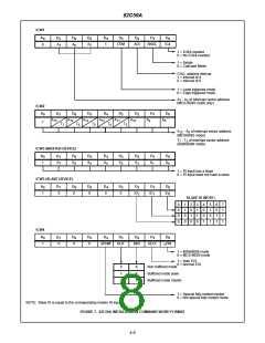
ICW1
D7
T7
T7
T7
T7
T7
T7
T7
T7
D6
T6
T6
T6
T6
T6
T6
T6
T6
D5
T5
T5
T5
T5
T5
T5
T5
T5
D4
T4
T4
T4
T4
T4
T4
T4
T4
D3
T3
T3
T3
T3
T3
T3
T3
T3
D2
1
D1
1
D0
1
lR7
lR6
IR5
IR4
IR3
IR2
IR1
IR0
1
1
0
ICW2
1
0
1
1
0
0
0
1
1
IN
NO (SNGL = 1)
0
1
0
CASCADE
MODE
0
0
1
0
0
0
YES (SNGL = 0))
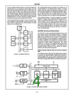
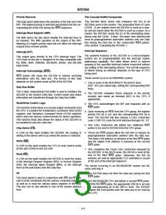
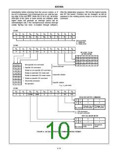
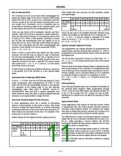
Programming the 82C59A
ICW3
The 82C59A accepts two types of command words gener-
ated by the CPU:
NO (IC4 = 0)
1. Initialization Command Words (ICWs): Before normal
operation can begin, each 82C59A in the system must be
brought to a starting point - by a sequence of 2 to 4 bytes
timed by WR pulses.
IS ICW4
NEEDED
YES (IC4 = 1)
2. Operation Command Words (OCWs): These are the
command words which command the 82C59A to operate
in various interrupt modes. Among these modes are:
ICW4
a. Fully nested mode.
b. Rotating priority mode.
c. Special mask mode.
d. Polled mode.
READY TO ACCEPT
INTERRUPT REQUESTS
FIGURE 6. 82C59A INITIALIZATION SEQUENCE
Initialization Command Words 1 and 2 (ICW1, lCW2)
The OCWs can be written into the 82C59A anytime after ini-
tialization.
A5 - A15: Page starting address of service routines. In an
8080/85 system the 8 request levels will generate CALLS to
8 locations equally spaced in memory. These can be pro-
grammed to be spaced at intervals of 4 or 8 memory loca-
tions, thus, the 8 routines will occupy a page of 32 or 64
bytes, respectively.
4-7

 INTERSIL [ Intersil ]