82C59A
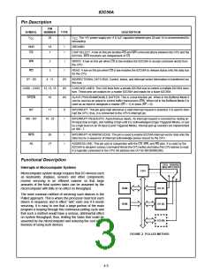
A more desirable method would be one that would allow the The Programmable Interrupt Controller (PlC) functions as an
microprocessor to be executing its main program and only overall manager in an Interrupt-Driven system. It accepts
stop to service peripheral devices when it is told to do so by requests from the peripheral equipment, determines which
the device itself. In effect, the method would provide an of the incoming requests is of the highest importance (prior-
external asynchronous input that would inform the processor ity), ascertains whether the incoming request has a higher
that it should complete whatever instruction that is currently priority value than the level currently being serviced, and
being executed and fetch a new routine that will service the issues an interrupt to the CPU based on this determination.
requesting device. Once this servicing is complete, however,
Each peripheral device or structure usually has a special
the processor would resume exactly where it left off.
program or “routine” that is associated with its specific func-
This is the Interrupt-driven method. It is easy to see that sys- tional or operational requirements; this is referred to as a
tem throughput would drastically increase, and thus, more “service routine”. The PlC, after issuing an interrupt to the
tasks could be assumed by the microcomputer to further CPU, must somehow input information into the CPU that can
enhance its cost effectiveness.
“point” the Program Counter to the service routine associ-
ated with the requesting device. This “pointer” is an address
in a vectoring table and will often be referred to, in this docu-
ment, as vectoring data.
INT
CPU
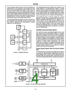
82C59A Functional Description
PIC
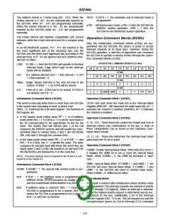
The 82C59A is a device specifically designed for use in real
time, interrupt driven microcomputer systems. It manages
eight levels of requests and has built-in features for expand-
ability to other 82C59As (up to 64 levels). It is programmed
by system software as an I/O peripheral. A selection of prior-
ity modes is available to the programmer so that the manner
in which the requests are processed by the 82C59A can be
configured to match system requirements. The priority
modes can be changed or reconfigured dynamically at any
time during main program operation. This means that the
complete interrupt structure can be defined as required,
based on the total system environment.
I/O (1)
RAM
ROM
I/O (2)
I/O (N)
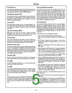
Interrupt Request Register (IRR) and In-Service Register
(ISR)
The interrupts at the IR input lines are handled by two registers
in cascade, the Interrupt Request Register (lRR) and the In-
Service Register (lSR). The IRR is used to indicate all the inter-
rupt levels which are requesting service, and the ISR is used to
store all the interrupt levels which are currently being serviced.
FIGURE 3. INTERRUPT METHOD
INTA
INT
DATA
BUS
D
- D
0
7
CONTROL LOGIC
BUFFER
IR0
IR1
IR2
IR3
IR4
IR5
IR6
IR7
RD
READ/
WRITE
LOGIC
WR
IN
INTERRUPT
REQUEST
REG
A
SERVICE
REG
PRIORITY
RESOLVER
0
(ISR)
(IRR)
CS
CASCADE
BUFFER
COMPARATOR
CAS 0
CAS 1
CAS 2
INTERRUPT MASK REG
(IMR)
SP/EN
INTERNAL BUS
FIGURE 4. 82C59A FUNCTIONAL DIAGRAM
4-4

 INTERSIL [ Intersil ]