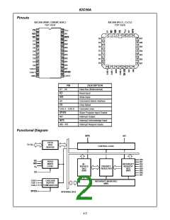
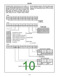
82C59A
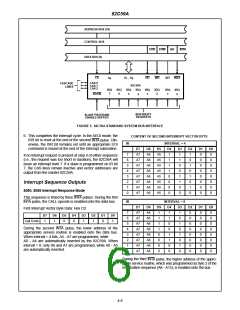
ADDRESS BUS (16)
CONTROL BUS
I/OR
I/OW
INT
INTA
DATA BUS (8)
CS
A
D
- D
0
RD
WR
INT
INTA
0
7
CAS 0
CASCADE
LINES
82C59A
CAS 1
CAS 2
IRQ
7
IRQ
6
IRQ
5
IRQ
4
IRQ
3
IRQ
2
IRQ
1
IRQ
0
SP/EN
INTERRUPT
REQUESTS
SLAVE PROGRAM/
ENABLE BUFFER
FIGURE 5. 82C59A STANDARD SYSTEM BUS INTERFACE
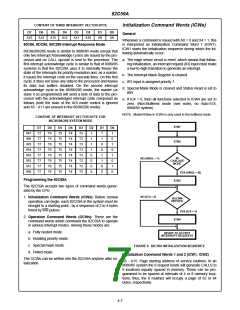
6. This completes the interrupt cycle. In the AEOI mode, the
ISR bit is reset at the end of the second INTA pulse. Oth-
erwise, the ISR bit remains set until an appropriate EOI
command is issued at the end of the interrupt subroutine.
CONTENT OF SECOND INTERRUPT VECTOR BYTE
INTERVAL = 4
IR
D7
A7
A7
A7
A7
A7
A7
A7
A7
D6
A6
A6
A6
A6
A6
A6
A6
A6
D5
A5
A5
A5
A5
A5
A5
A5
A5
D4
1
D3
1
D2
1
D1
0
D0
0
7
6
5
4
3
2
1
0
If no interrupt request is present at step 4 of either sequence
(i.e., the request was too short in duration), the 82C59A will
issue an interrupt level 7. If a slave is programmed on IR bit
7, the CAS lines remain inactive and vector addresses are
output from the master 82C59A.
1
1
0
0
0
1
0
1
0
0
1
0
0
0
0
0
1
1
0
0
0
1
0
0
0
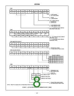
Interrupt Sequence Outputs
0
0
1
0
0
8080, 8085 Interrupt Response Mode
0
0
0
0
0
This sequence is timed by three INTA pulses. During the first
lNTA pulse, the CALL opcode is enabled onto the data bus.
IR
INTERVAL = 8
D7
A7
A7
A7
A7
A7
A7
A7
A7
D6
A6
A6
A6
A6
A6
A6
A6
A6
DS
1
D4
1
D3
1
D2
0
D1
0
D0
0
First Interrupt Vector Byte Data: Hex CD
7
6
5
4
3
2
1
0
D7
D6
D5
D4
D3
D2
D1
D0
1
1
0
0
0
0
Call Code
1
1
0
0
1
1
0
1
1
0
1
0
0
0
During the second INTA pulse, the lower address of the
appropriate service routine is enabled onto the data bus.
When interval = 4 bits, A5 - A7 are programmed, while
A0 - A4 are automatically inserted by the 82C59A. When
interval = 8, only A6 and A7 are programmed, while A0 - A5
are automatically inserted.
1
0
0
0
0
0
0
1
1
0
0
0
0
1
0
0
0
0
0
0
1
0
0
0
0
0
0
0
0
0
During the third INTA pulse, the higher address of the appro-
priate service routine, which was programmed as byte 2 of the
initialization sequence (A8 - A15), is enabled onto the bus.
4-6

 INTERSIL [ Intersil ]