82C59A
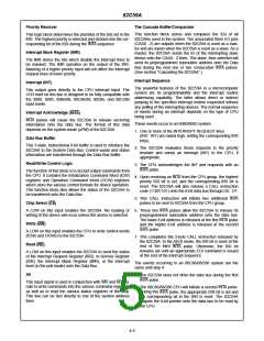
The address format is 2 bytes long (A0 - A15). When the AEOI: If AEOI = 1, the automatic end of interrupt mode is
routine interval is 4, A0 - A4 are automatically inserted by
the 82C59A, while A5 - A15 are programmed externally.
When the routine interval is 8, A0 - A5 are automatically
inserted by the 82C59A while A6 - A15 are programmed
externally.
programmed.
µPM: Microprocessor mode: µPM = 0 sets the 82C59A for
8080/85 system operation, µPM = 1 sets the
82C59A for 80C86/88/286 system operation.
The 8-byte interval will maintain compatibility with current
software, while the 4-byte interval is best for a compact jump
table.
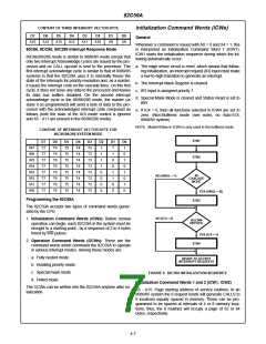
Operation Command Words (OCWs)
After the Initialization Command Words (lCWs) are pro-
grammed into the 82C59A, the device is ready to accept
interrupt requests at its input lines. However, during the
82C59A operation, a selection of algorithms can command
the 82C59A to operate in various modes through the Opera-
tion Command Words (OCWs).
In an 80C86/88/286 system, A15 - A11 are inserted in the
five most significant bits of the vectoring byte and the
82C59A sets the three least significant bits according to the
interrupt level. A10 - A5 are ignored and ADI (Address inter-
val) has no effect.
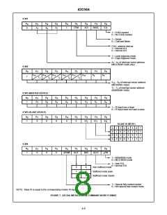
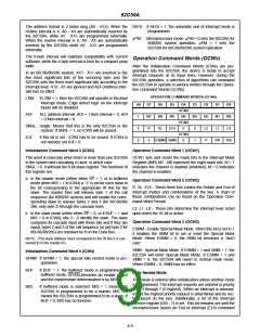
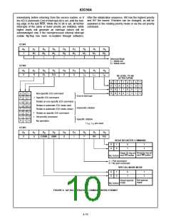
OPERATION COMMAND WORDS (OCWs)
LTlM: If LTlM = 1, then the 82C59A will operate in the level
interrupt mode. Edge detect logic on the interrupt
inputs will be disabled.
A0
1
D7
M7
R
D6
M6
SL
D5
D4
OCW1
M4
D3
M3
0
D2
M2
L2
P
D1
M1
L1
D0
M0
L0
ADI:
ALL address interval. ADI = 1 then interval = 4; ADI
= 0 then interval = 8.
M5
OCW2
0
SNGL: Single. Means that this is the only 82C59A in the
system. If SNGL = 1, no ICW3 will be issued.
0
EOI
OCW3
0
IC4:
If this bit is set - lCW4 has to be issued. If lCW4 is
not needed, set lC4 = 0.
0
0
ESMM SMM
1
RR
RIS
Initialization Command Word 3 (ICW3)
Operation Command Word 1 (OCW1)
This word is read only when there is more than one 82C59A OCW1 sets and clears the mask bits in the Interrupt Mask
in the system and cascading is used, in which case Register (lMR) M7 - M0 represent the eight mask bits. M = 1
SNGL = 0. It will load the 8-bit slave register. The functions of indicates the channel is masked (inhibited), M = 0 indicates
this register are:
the channel is enabled.
a. In the master mode (either when SP = 1, or in buffered
mode when M/S = 1 in lCW4) a “1” is set for each slave in
the bit corresponding to the appropriate IR line for the
slave. The master then will release byte 1 of the call
sequence (for 8080/85 system) and will enable the corre-
sponding slave to release bytes 2 and 3 (for 80C86/88/
286, only byte 2) through the cascade lines.
Operation Command Word 2 (OCW2)
R, SL, EOI - These three bits control the Rotate and End of
Interrupt modes and combinations of the two. A chart of
these combinations can be found on the Operation Com-
mand Word Format.
L2, L1, L0 - These bits determine the interrupt level acted
b. In the slave mode (either when SP = 0, or if BUF = 1 and upon when the SL bit is active.
M/S = 0 in lCW4), bits 2 - 0 identify the slave. The slave
Operation Command Word 3 (OCW3)
compares its cascade input with these bits and if they are
equal, bytes 2 and 3 of the call sequence (or just byte 2 for
80C86/88/286) are released by it on the Data Bus.
ESMM - Enable Special Mask Mode. When this bit is set to 1
it enables the SMM bit to set or reset the Special Mask
Mode. When ESMM = 0, the SMM bit becomes a “don’t
care”.
NOTE: (The slave address must correspond to the IR line it is con-
nected to in the master ID).
SMM - Special Mask Mode. If ESMM = 1 and SMM = 1, the
82C59A will enter Special Mask Mode. If ESMM = 1 and
SMM = 0, the 82C59A will revert to normal mask mode.
When ESMM = 0, SMM has no effect.
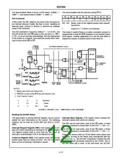
Initialization Command Word 4 (ICW4)
SFNM: If SFNM = 1, the special fully nested mode is pro-
grammed.
BUF: If BUF = 1, the buffered mode is programmed. In
buffered mode, SP/EN becomes an enable output
and the master/slave determination is by M/S.
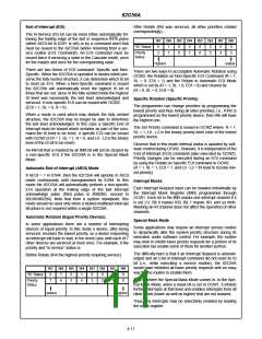
Fully Nested Mode
This mode is entered after initialization unless another mode
is programmed. The interrupt requests are ordered in priority
from 0 through 7 (0 highest). When an interrupt is acknowl-
edged the highest priority request is determined and its vec-
tor placed on the bus. Additionally, a bit of the Interrupt
Service register (IS0 - 7) is set. This bit remains set until the
microprocessor issues an End of Interrupt (EOI) command
M/S:
If buffered mode is selected: M/S = 1 means the
82C59A is programmed to be a master, M/S = 0
means the 82C59A is programmed to be a slave. If
BUF = 0, M/S has no function.
4-9

 INTERSIL [ Intersil ]