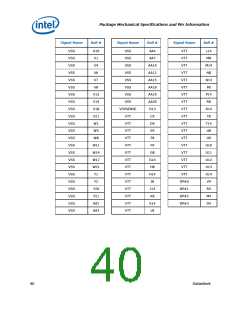
Package Mechanical Specifications and Pin Information
Signal Name
Type
Description
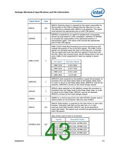
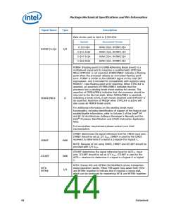
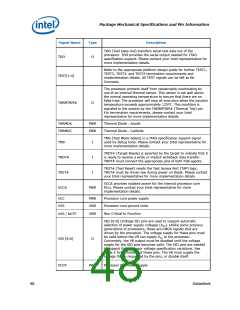
Data strobe used to latch in D [63:0]#.
Signals
Associated Strobe
D [15:0]#
D [31:16]#
D [47:32]#
D [63:48]#
DINV [0]#, DSTBP [0]#
DINV [1]#, DSTBP [1]#
DINV [2]#, DSTBP [2]#
DINV [3]#, DSTBP [3]#
DSTBP [3:0]#
I/O
FERR# (Floating-point Error)PBE#(Pending Break Event) is a
multiplexed signal and its meaning is qualified with STPCLK#.
When STPCLK# is not asserted, FERR#/PBE# indicates a floating
point when the processor detects an unmasked floating-point
error. FERR# is similar to the ERROR# signal on the Intel 387
coprocessor, and is included for compatibility with systems using
MSDOS*- type floating-point error reporting. When STPCLK# is
asserted, an assertion of FERR#/PBE# indicates that the
processor has a pending break event waiting for service. The
assertion of FERR#/PBE# indicates that the processor should be
returned to the Normal state. When FERR#/PBE# is asserted,
indicating a break event, it will remain asserted until STPCLK# is
de-asserted. Assertion of PREQ# when STPCLK# is active will
also cause an FERR# break event.
FERR#/PBE#
O
For additional information on the pending break event
functionality, including identification of support of the feature and
enable/disable information, refer to Volume 3 of the Intel® 64
and IA-32 Architectures Software Developer's Manuals and the
Intel® Processor Identification and CPUID Instruction Application
Note.
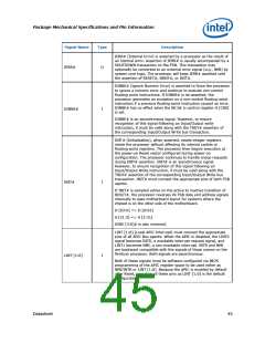
For termination requirements please contact your Intel
representative.
CMREF determines the signal reference level for CMOS input pins.
CMREF should be set at 1/2 VCCP. CMREF is used by the CMOS
receivers to determine if a signal is a logical-0 or logical-1.
CMREF
PWR
NOTE: Because of not using CMOS, CMREF and GTLREF should be
provided with 2/3 VCCP
.
GTLREF determines the signal reference level for AGTL+ input
pins. GTLREF should be set at 2/3 VCCP. GTLREF is used by the
AGTL+ receivers to determine if a signal is a logical-0 or logical-
1.
GTLREF
PWR
I/O
HIT# (Snoop Hit) and HITM# (Hit Modified) convey transaction
snoop operation results. Either FSB agent may assert both HIT#
and HITM# together to indicate that it requires a snoop stall,
which can be continued by reasserting HIT# and HITM# together.
HIT#
HITM#
44
Datasheet

 INTEL [ INTEL ]