1-Gbit P30 Family
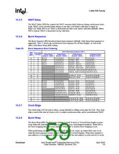
Table 22.
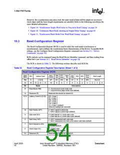
Read Configuration Register Description (Sheet 2 of 2)
3
Burst Wrap (BW)
0 =Wrap; Burst accesses wrap within burst length set by BL[2:0]
1 =No Wrap; Burst accesses do not wrap within burst length (default)
2:0
Burst Length (BL[2:0])
001 =4-word burst
010 =8-word burst
011 =16-word burst
111 =Continuous-word burst (default)
(Other bit settings are reserved)
Note: Latency Code 2, Data Hold for a 2-clock data cycle (DH = 1) WAIT must be deasserted with valid data (WD =
0). Latency Code 2, Data Hold for a 2-cock data cycle (DH=1) WAIT deasserted one data cycle before valid
data (WD = 1) combination is not supported.
10.3.1
10.3.2
Read Mode
The Read Mode (RM) bit selects synchronous burst-mode or asynchronous page-mode operation
for the device. When the RM bit is set, asynchronous page mode is selected (default). When RM is
cleared, synchronous burst mode is selected.
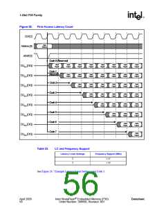
Latency Count
The Latency Count bits, LC[2:0], tell the device how many clock cycles must elapse from the
rising edge of ADV# (or from the first valid clock edge after ADV# is asserted) until the first data
word is to be driven onto DQ[15:0]. The input clock frequency is used to determine this value.
Figure 28 shows the data output latency for the different settings of LC[2:0].
Synchronous burst with a Latency Count setting of Code 4 will result in zero WAIT state; however,
a Latency Count setting of Code 5 will cause 1 WAIT state (Code 6 will cause 2 WAIT states, and
Code 7 will cause 3 WAIT states) after every four words, regardless of whether a 16-word
boundary is crossed. If RCR[9] (Data Hold) bit is set (data hold of two clocks) this WAIT condition
will not occur because enough clocks elapse during each burst cycle to eliminate subsequent WAIT
states.
Refer to Table 23, “LC and Frequency Support” on page 56 for Latency Code Settings.
Datasheet
Intel StrataFlash® Embedded Memory (P30)
Order Number: 306666, Revision: 001
April 2005
55

 INTEL [ INTEL ]