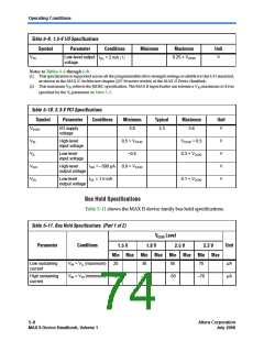
Timing Model & Specifications
Performance
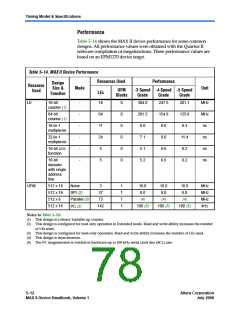
Table 5–14 shows the MAX II device performance for some common
designs. All performance values were obtained with the Quartus II
software compilation of megafunctions. These performance values are
based on an EPM1270 device target.
Table 5–14. MAX II Device Performance
Resources Used
Performance
Design
Size &
Function
Resource
Used
Mode
Unit
UFM
LEs
-3 Speed -4 Speed -5 Speed
Blocks
Grade
Grade
Grade
LE
16-bit
counter (1)
-
-
-
-
-
-
16
64
11
24
5
0
0
0
0
0
0
304.0
247.5
201.1
MHz
MHz
ns
64-bit
counter (1)
201.5
6.0
154.8
8.0
125.8
9.3
16-to-1
multiplexer
32-to-1
multiplexer
7.1
9.0
11.4
8.2
ns
16-bit XOR
function
5.1
6.6
ns
16-bit
5
5.2
6.6
8.2
ns
decoder
with single
address
line
UFM
512 x 16
512 x 16
512 x 8
None
3
1
1
1
1
10.0
8.0
10.0
8.0
10.0
8.0
MHz
MHz
MHz
kHz
SPI (2)
37
Parallel (3)
I2C (3)
73
(4)
(4)
(4)
512 x 16
142
100 (5)
100 (5)
100 (5)
Notes to Table 5–14:
(1) This design is a binary loadable up counter.
(2) This design is configured for read only operation in Extended mode. Read and write ability increases the number
of LEs used.
(3) This design is configured for read-only operation. Read and write ability increases the number of LEs used.
(4) This design is asynchronous.
(5) The I2C megafunction is verified in hardware up to 100-kHz serial clock line (SCL) rate.
5–12
Core Version a.b.c variable
Altera Corporation
July 2006
MAX II Device Handbook, Volume 1

 INTEL [ INTEL ]