DC & Switching Characteristics
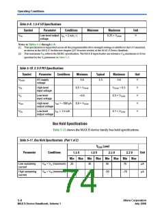
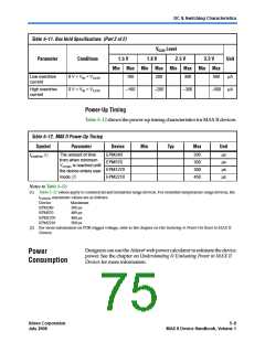
Table 5–11. Bus Hold Specifications (Part 2 of 2)
VCCIO Level
1.8 V 2.5 V
Min Max Min Max Min Max Min Max
Parameter
Conditions
Unit
1.5 V
3.3 V
Low overdrive
current
0 V < VIN < VCCIO
0 V < VIN < VCCIO
160
200
300
500
μA
μA
High overdrive
current
–160
–200
–300
–500
Power-Up Timing
Table 5–12 shows the power-up timing characteristics for MAX II devices.
Table 5–12. MAX II Power-Up Timing
Symbol
Parameter
Device
Min
Typ
Max
Unit
The amount of time
from when minimum
VCCINT is reached until
the device enters user
mode (2)
EPM240
EPM570
EPM1270
EPM2210
200
300
300
450
μs
μs
μs
μs
tCONFIG (1)
Notes to Table 5–12:
(1) Table 5–12 values apply to commercial and industrial range devices. For extended temperature range devices, the
CONFIG maximum values are as follows:
t
Device
Maximum
300 µs
400 µs
400 µs
500 µs
EPM240
EPM570
EPM1270
EPM2210
(2) For more information on POR trigger voltage, refer to the chapter on Hot Socketing & Power-On Reset in MAX II
Devices.
®
Designers can use the Altera web power calculator to estimate the device
Power
Consumption
power. See the chapter on Understanding & Evaluating Power in MAX II
Devices for more information.
Altera Corporation
July 2006
Core Version a.b.c variable
5–9
MAX II Device Handbook, Volume 1

 INTEL [ INTEL ]