Chapter 1: Cyclone IV Device Datasheet
1–21
Switching Characteristics
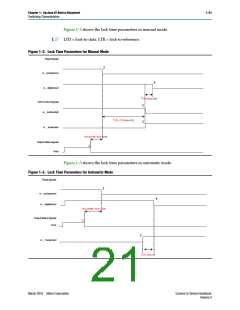
Figure 1–2 shows the lock time parameters in manual mode.
LTD = lock-to-data. LTR = lock-to-reference.
1
Figure 1–2. Lock Time Parameters for Manual Mode
Reset Signals
2
rx _analogreset
4
rx _ digitalreset
tLTD_Manual (2)
CDR Control Signals
rx _ locktorefclk
3
tLTR_LTD_Manual (1)
3
rx _ locktodata
Two parallel clock cycles
Output Status Signals
1
busy
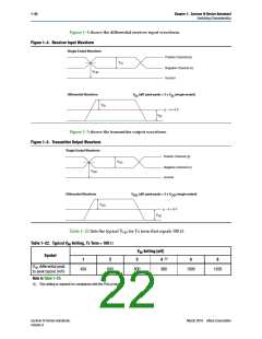
Figure 1–3 shows the lock time parameters in automatic mode.
Figure 1–3. Lock Time Parameters for Automatic Mode
Reset Signals
2
rx _analogreset
rx _ digitalreset
4
Two parallel clock cycles
Output Status Signals
busy
1
3
rx _ freqlocked
tLTD_Auto (1)
March 2016 Altera Corporation
Cyclone IV Device Handbook,
Volume 3

 INTEL [ INTEL ]