Chapter 1: Cyclone IV Device Datasheet
1–19
Switching Characteristics
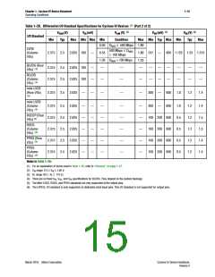
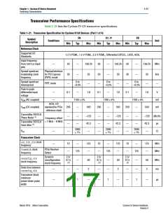
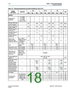
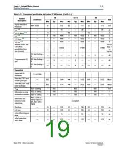
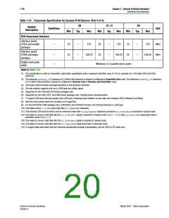
Table 1–21. Transceiver Specification for Cyclone IV GX Devices (Part 3 of 4)
C6
C7, I7
Typ
C8
Symbol/
Conditions
Description
Unit
Min
Typ
Max
Min
Max
Min
Typ
Max
Signal detect/loss
threshold
PIPE mode
65
—
175
65
—
175
65
—
175
mV
(10)
tLTR
—
—
—
—
—
—
15
0
—
—
75
—
15
0
—
—
75
—
15
0
—
—
75
µs
µs
ns
ns
ns
(11)
tLTR-LTD_Manual
—
—
—
(12)
tLTD
100
—
4000
4000
4000
100
—
4000
4000
4000
100
—
4000
4000
4000
(13)
tLTD_Manual
—
—
—
—
—
—
(14)
tLTD_Auto
—
—
—
Receiver buffer and
CDR offset
cancellation time
(per channel)
recon
fig_c
lk
—
—
—
17000
—
—
17000
—
—
17000
cycles
DC Gain Setting =
0
—
—
—
0
3
6
—
—
—
—
—
—
0
3
6
—
—
—
—
—
—
0
3
6
—
—
—
dB
dB
dB
Programmable DC
gain
DC Gain Setting =
1
DC Gain Setting =
2
Transmitter
Supported I/O
Standards
1.5 V PCML
Data rate (F324 and
smaller package)
—
—
600
600
—
—
2500
3125
600
600
—
—
2500
3125
600
600
—
—
2500
2500
Mbps
Mbps
Data rate (F484 and
larger package)
VOCM
0.65 V setting
100 setting
150 setting
—
—
—
650
100
150
—
—
—
—
—
—
650
100
150
—
—
—
—
—
—
650
100
150
—
—
—
mV
Differential on-chip
termination resistors
PIPE, CPRI LV,
Serial Rapid I/O
SR, SDI, XAUI,
SATA
Differential and
common mode
return loss
Compliant
—
Rise time
Fall time
—
—
50
50
—
—
200
200
50
50
—
—
200
200
50
50
—
—
200
200
ps
ps
Intra-differential pair
skew
—
—
—
—
—
—
15
—
—
—
—
15
—
—
—
—
15
ps
ps
Intra-transceiver
block skew
120
120
120
March 2016 Altera Corporation
Cyclone IV Device Handbook,
Volume 3

 INTEL [ INTEL ]