1–18
Chapter 1: Cyclone IV Device Datasheet
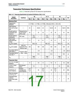
Switching Characteristics
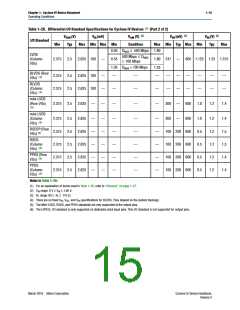
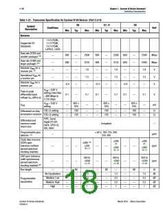
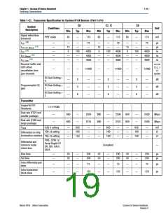
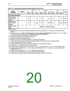
Table 1–21. Transceiver Specification for Cyclone IV GX Devices (Part 2 of 4)
C6
C7, I7
Typ
C8
Symbol/
Conditions
Description
Unit
Min
Typ
Max
Min
Max
Min
Typ
Max
Receiver
1.4 V PCML,
1.5 V PCML,
2.5 V PCML,
LVPECL, LVDS
Supported I/O
Standards
Data rate (F324 and
smaller package) (15)
—
—
—
—
—
600
600
—
—
—
—
—
—
2500
3125
1.6
600
600
—
—
—
—
—
—
2500
3125
1.6
600
600
—
—
—
—
—
—
2500
2500
1.6
Mbps
Data rate (F484 and
larger package) (15)
Mbps
Absolute VMAX for a
V
V
V
(3)
receiver pin
Operational VMAX for
a receiver pin
—
1.5
—
1.5
—
1.5
Absolute VMIN for a
receiver pin
–0.4
—
–0.4
—
–0.4
—
VICM = 0.82 V
setting, Data Rate
= 600 Mbps to
3.125 Gbps
Peak-to-peak
differential input
voltage VID (diff p-p)
0.1
—
2.7
—
0.1
—
2.7
—
0.1
—
2.7
—
V
V
ICM = 0.82 V
820
10%
820
10%
820
10%
VICM
—
—
—
mV
setting
100 setting
150 setting
—
—
100
150
—
—
—
—
100
150
—
—
—
—
100
150
—
—
Differential on-chip
termination resistors
PIPE, Serial
Rapid I/O SR,
SATA, CPRI LV,
SDI, XAUI
Differential and
common mode
return loss
Compliant
—
Programmable ppm
detector
62.5, 100, 125, 200,
250, 300
—
ppm
(4)
Clock data recovery
(CDR) ppm
tolerance (without
spread-spectrum
clocking enabled)
300
300
,
(5),
300
(5),
(5)
—
—
—
—
—
350
—
—
—
—
—
—
ppm
350
350
(6), (7)
(6), (7)
(6), (7)
CDR ppm tolerance
(with synchronous
spread-spectrum
350 to
350 to
350 to
—
–5350
—
—
–5350
–5350
ppm
(7), (9)
(7), (9)
(7), (9)
clocking enabled) (8)
Run length
—
—
—
—
—
—
80
—
—
—
—
—
1.5
4.5
5.5
7
—
—
—
—
—
80
—
—
—
—
—
1.5
4.5
5.5
7
—
—
—
—
—
80
—
—
—
—
—
1.5
4.5
5.5
7
UI
dB
dB
dB
dB
No Equalization
Medium Low
Medium High
High
Programmable
equalization
Cyclone IV Device Handbook,
Volume 3
March 2016 Altera Corporation

 INTEL [ INTEL ]