Processor Configuration Registers
2.13.2
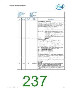
TC_RAP_C0—Timing of DDR – Regular Access Parameters
Register
Thie register is for the regular timing parameters in DCLK cycles.
B/D/F/Type:
Address Offset:
Reset Value:
Access:
0/0/0/MCHBAR MC0
4004–4007h
86104344h
RW-L
Size:
32 bits
Reset
Value
RST/
PWR
Bit
Access
Description
1n 2N or 3N selection (CMD_stretch)
This field defines the operation mode of the command.
00 = N operation
10 = 2N operation
11 = 3N operation
31:30
RW-L
10b
0b
Uncore
Uncore
Command 3-state options (CMD_3st)
This bit defines when command & address bus is driving.
0 = Drive when channel is active. Tri-stated when all ranks are in
CKE-off or when memory is in SR or deeper.
29
RW-L
1 = Command bus is always driving. When no new valid
command is driven, previous command & address is driven
tWR in DCLK cycles (tWR)
Write recovery time. The range is 5 to 16 DCLK cycles.
28:24
23:16
RW-L
RW-L
06h
10h
Uncore
Uncore
tFAW in DCLK cycles (tFAW)
Four-activate window is the time frame in which maximum of 4
ACT commands to the same rank are allowed. The minimum
value is 4*tRRD, whereas the maximum value is 63 DCLK cycles.
tWTR in DCLK cycles (tWTR)
Delay from internal WR transaction to internal RD transaction.
The minimum delay is 4 DCLK cycles, whereas the maximum
delay is 8 DCLK cycles.
15:12
RW-L
4h
Uncore
tCKE in DCLK cycles (tCKE)
CKE minimum pulse width in DCLK cycles. The minimum value is
3 DCLK cycles, whereas the maximum value is the actual value of
tXP.
11:8
7:4
RW-L
RW-L
RW-L
3h
4h
4h
Uncore
Uncore
Uncore
tRTP in DCLK cycles (tRTP)
Minimum delay from CAS-RD to PRE. The minimum delay is 4
DCLK cycles, whereas the maximum delay is 8 DCLK cycles.
tRRD in DCLK cycles (tRRD)
tRRD is the minimum delay between two ACT commands
targeted to different banks in the same rank. The minimum delay
is 4 DCLK cycles, whereas the maximum delay is 7 cycles.
3:0
Datasheet, Volume 2
241

 INTEL [ INTEL ]