®
Intel ICH10 Pin States
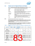
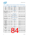
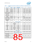
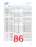
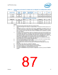
Table 3-2.
Power Plane and States for Output and I/O Signals for Configurations (Sheet
5 of 5)
Power
Plane
During
Reset4
Immediately
after Reset4
Signal Name
C3/C4
S1
S3
S4/S5
Controller
Link
CL_DATA0
CL_RST0#
Low
Low
Low
Defined10 Defined10 Defined10
Defined10 Defined10 Defined10
Suspend
High
Intel® Quiet System Technology
PWM[2:0]
SST
Core
High-Z
High-Z
High-Z
Low
Low
Low
Defined
Defined
Defined
Off
Off
Off
Off
Off
Off
Controller
Link
PECI
CPU
NOTES:
1. ICH10 drives these signals High after the processor Reset
2.
GPIO[18] will toggle at a frequency of approximately 1 Hz when the ICH10 comes out of
reset
3.
CPUPWRGD represents a logical AND of the ICH10’s VRMPWRGD and PWROK signals, and
thus will be driven low by ICH10 when either VRMPWRGD or PWROK are inactive. During
boot, or during a hard reset with power cycling, CPUPWRGD will be expected to transition
from low to High-Z.
4.
The states of Core and processor signals are evaluated at the times During PLTRST# and
Immediately after PLTRST#. The states of the LAN and GLAN signals are evaluated at the
times During LAN_RST# and Immediately after LAN_RST#. The states of the Controller
Link signals are taken at the times During CL_RST# and Immediately after CL_RST#. The
states of the Suspend signals are evaluated at the times During RSMRST# and
Immediately after RSMRST#. The states of the HDA signals are evaluated at the times
During HDA_RST# and Immediately after HDA_RST#.
5.
6.
7.
ICH10 drives these signals Low before PWROK rising and Low after the processor Reset.
SLP_S5# signals will be high in the S4 state.
Low until Intel High Definition Audio Controller Reset bit set (D27:F0:Offset
HDBAR+08h:bit 0), at which time HDA_RST# will be High and HDA_BIT_CLK will be
Running.
8.
PETp/n[6:1] high until port is enabled by software.
9.
The SLP_M# state will be determined by Intel AMT Policies.
10.
11.
12.
The state of signals in S3-5 will be defined by Intel AMT Policies.
This signal is sampled as a functional strap during reset.
The state of DRAMPWROK during S3/S4/S5 is dependent on the SLP_S4# and CLPWROK
signals.
Datasheet
87

 INTEL [ INTEL ]