®
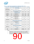
Intel ICH10 Pin States
Table 3-3.
Power Plane for Input Signals for Configurations (Sheet 3 of 3)
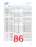
Signal Name
Power Well Driver During Reset
SMBus Interface
C3/C4
S1
S3
S4/S5
SMBALERT# /
GPIO11 / JTAGTDO1
(Corporate Only)
Suspend
RTC
External Pull-up
Driven
Driven
Driven
High
Driven
High
System Management Interface
External Switch
INTRUDER#
Miscellaneous Signals
INTVRMEN
LAN100_SLP
RTCRST#
RTC
RTC
RTC
RTC
External Pull-up
External Pull-up
High
High
High
High
High
High
High
High
High
High
High
High
External RC Circuit
External RC Circuit
SRTCRST#
Consumer Only:
External Circuit2
Controller
Link
CL_VREF0
Driven
High
Driven
High
Driven
High
Corporate Only:
Internal Circuit3
TP0 / GPIO72
(Corporate Only)
Suspend
External Pull-up
Intel® High Definition Audio Interface
Intel High Definition
HDA_SDIN[3:0]
SPI_MISO
Suspend
Low
Low
Driven
Off
Low
Driven
Off
Audio Codec
SPI Interface
Controller
Link
Internal Pull-up
Intel® Quiet System Technology
External Pull-up
Driven
Driven
TACH[3:0]/
Core
GPIO[7,6,1,17]1
Clocks
CLK14
CLK48
Core
Core
Clock Generator
Clock Generator
Running
Running
Off
Off
Off
Off
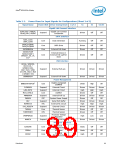
NOTES:
1.
2.
3.
These signals can be configured as outputs in GPIO mode.The state of the DPRSLPVR and
DPRSTP# signals in C4 are high if Deeper Sleep is enabled or low if it is disabled.
Consumer Only: CL_VREF0 is driven by an external circuit except on platforms where the
MCH does not support Controller Link. In these platforms, the signal is not driven.
Corporate Only: CL_VREF0 may optionally be driven by an external circuit, as configured
by CLINKVREFSEL (ICHSTRP0:bit 5).
§ §
90
Datasheet

 INTEL [ INTEL ]