®
Intel ICH10 Pin States
3.2
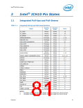
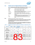
Output and I/O Signals Planes and States
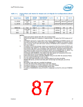
Table 3-2 shows the power plane associated with the output and I/O signals, as well as
the state at various times. Within the table, the following terms are used:
“High-Z”
“High”
Tri-state. ICH10 not driving the signal high or low.
ICH10 is driving the signal to a logic 1.
ICH10 is driving the signal to a logic 0.
“Low”
“Defined”
Driven to a level that is defined by the function or external pull-
up/pull-down resistor (will be high or low).
“Undefined”
“Running”
ICH10 is driving the signal, but the value is indeterminate.
Clock is toggling or signal is transitioning because function not
stopping.
“Off”
The power plane is off; ICH10 is not driving when configured as
an output or sampling when configured as an input.
“Input”
ICH10 is sampling and signal state determined by external
driver.
Note:
Signal levels are the same in S4 and S5, except as noted.
The ICH10 suspend well signal states are indeterminate and undefined and may glitch
prior to RSMRST# deassertion. This does not apply to LAN_RST#, SLP_S3#, SLP_S4#,
S4_STATE# and SLP_S5#. These signals are determinate and defined prior to
RSMRST# deassertion.
The ICH10 core well signal states are indeterminate and undefined and may glitch prior
to PWROK assertion. This does not apply to FERR# and THRMTRIP#. These signals are
determinate and defined prior to PWROK assertion.
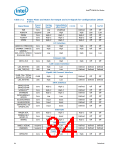
Table 3-2.
Power Plane and States for Output and I/O Signals for Configurations (Sheet
1 of 5)
Power
Plane
During
Reset4
Immediately
after Reset4
Signal Name
C3/C4
S1
S3
S4/S5
PCI Express*
PETp[5:1],
PETn[5:1],
Core
Core
High
High
High8
Defined
Defined
Off
Off
Off
Off
PETp6 / GLANTXp,
PETn6 / GLANTXn
DMI
High
DMI[3:0]TXP,
DMI[3:0]TXN
PCI Bus
AD[31:0]
C/BE[3:0]#
DEVSEL#
FRAME#
Core
Core
Core
Core
Low
Low
Undefined
Undefined
High-Z
Defined
Defined
High-Z
High-Z
Off
Off
Off
Off
Off
Off
Off
Off
High-Z
High-Z
High-Z
GNT0#11
,
GNT[3:1]#11
/
Core
Core
High-Z
High-Z
High
High
Off
Off
Off
Off
GPIO[55, 53, 51]
IRDY#, TRDY#
High-Z
High-Z
Datasheet
83

 INTEL [ INTEL ]