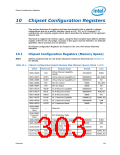
Chipset Configuration Registers
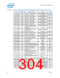
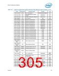
Table 10-1. Chipset Configuration Register Memory Map (Memory Space) (Sheet 4 of 4)
Offset
Mnemonic
Register Name
Default
Type
350C-350Fh
3524–3525h
CIR9
PPO
Chipset Initialization Register 9
USB Port Power Off
00000000h
0000h
R/W
R/W
Chipset Initialization Register
10
352C-352Fh
35F0-35F3h
CIR10
MAP
0008C008hh
00000000h
R/W
USB Remap Control
R/WO
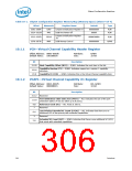
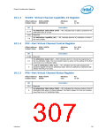
10.1.1
VCH—Virtual Channel Capability Header Register
Offset Address: 0000–0003h
Attribute:
Size:
R/WO
32-bit
Default Value:
10010002h
Bit
Description
31:20
19:16
15:0
Next Capability Offset (NCO) — R/WO. Indicates the next item in the list.
Capability Version (CV) — R/WO. Indicates support as a version 1 capability
structure.
Capability ID (CID) — R/WO. Indicates this is the Virtual Channel capability item.
10.1.2
VCAP1—Virtual Channel Capability #1 Register
Offset Address: 0004–0007h
Attribute:
Size:
RO, R/WO
32-bit
Default Value:
00000801h
Bit
Description
31:12
11:10
Reserved
Port Arbitration Table Entry Size (PATS) — RO. Indicates the size of the port
arbitration table is 4 bits (to allow up to 8 ports).
9:8
7
Reference Clock (RC) — RO. Fixed at 100 ns.
Reserved
Low Priority Extended VC Count (LPEVC) — RO. Indicates that there are no
additional VCs of low priority with extended capabilities.
6:4
3
Reserved
Extended VC Count (EVC) — R/WO. Indicates that there is one additional VC (VC1)
that exists with extended capabilities.
2:0
306
Datasheet

 INTEL [ INTEL ]