PCI Express* Registers (D1:F0)
6.1.26
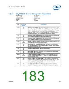
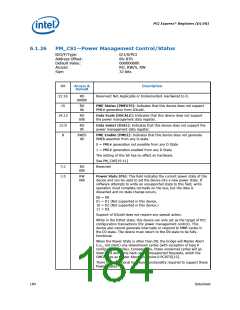
PM_CS1—Power Management Control/Status
B/D/F/Type:
Address Offset:
Default Value:
Access:
0/1/0/PCI
84–87h
00000000h
RO, RW/S, RW
32 bits
Size:
Bit
Access &
Default
Description
31:16
15
RO
0000h
Reserved: Not Applicable or Implemented. Hardwired to 0.
RO
0b
PME Status (PMESTS): Indicates that this device does not support
PME# generation from D3cold.
14:13
12:9
8
RO
00b
Data Scale (DSCALE): Indicates that this device does not support
the power management data register.
RO
0h
Data Select (DSEL): Indicates that this device does not support the
power management data register.
RW/S
0b
PME Enable (PMEE): Indicates that this device does not generate
PMEB assertion from any D-state.
0 = PME# generation not possible from any D State
1 = PME# generation enabled from any D State
The setting of this bit has no effect on hardware.
See PM_CAP[15:11]
7:2
1:0
RO
00h
Reserved
RW
00b
Power State (PS): This field indicates the current power state of this
device and can be used to set the device into a new power state. If
software attempts to write an unsupported state to this field, write
operation must complete normally on the bus, but the data is
discarded and no state change occurs.
00 = D0
01 = D1 (Not supported in this device.
10 = D2 (Not supported in this device.)
11 = D3
Support of D3cold does not require any special action.
While in the D3hot state, this device can only act as the target of PCI
configuration transactions (for power management control). This
device also cannot generate interrupts or respond to MMR cycles in
the D3 state. The device must return to the D0 state to be fully-
functional.
When the Power State is other than D0, the bridge will Master Abort
(i.e., not claim) any downstream cycles (with exception of type 0
configuration cycles). Consequently, these unclaimed cycles will go
down DMI and come back up as Unsupported Requests, which the
GMCH logs as Master Aborts in Device 0 PCISTS[13].
There is no additional hardware functionality required to support these
Power States.
184
Datasheet

 INTEL [ INTEL ]