PCI Express* Registers (D1:F0)
6.1.24
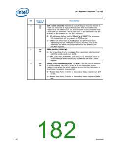
BCTRL1—Bridge Control
B/D/F/Type:
Address Offset:
Default Value:
Access:
0/1/0/PCI
3E–3Fh
0000h
RO, RW
16 bits
Size:
This register provides extensions to the PCICMD1 register that are specific to PCI-to-
PCI bridges. The BCTRL provides additional control for the secondary interface (i.e.,
PCI Express) as well as some bits that affect the overall behavior of the "virtual" Host-
PCI Express bridge in the GMCH (e.g., VGA compatible address ranges mapping).
Bit
15:12
11
10
9
Access &
Default
Description
RO
0h
Reserved
RO
0b
Discard Timer SERR# Enable (DTSERRE): Not Applicable or
Implemented. Hardwired to 0.
RO
0b
Discard Timer Status (DTSTS): Not Applicable or Implemented.
Hardwired to 0.
RO
0b
Secondary Discard Timer (SDT): Not Applicable or Implemented.
Hardwired to 0.
8
RO
0b
Primary Discard Timer (PDT): Not Applicable or Implemented.
Hardwired to 0.
7
RO
0b
Fast Back-to-Back Enable (FB2BEN): Not Applicable or
Implemented. Hardwired to 0.
6
RW
0b
Secondary Bus Reset (SRESET): Setting this bit triggers a hot reset
on the corresponding PCI Express Port. This will force the LTSSM to
transition to the Hot Reset state (via Recovery) from L0, L0s, or L1
states.
5
4
RO
0b
Master Abort Mode (MAMODE): Does not apply to PCI Express.
Hardwired to 0.
VGA 16-bit Decode (VGA16D): This bit enables the PCI-to-PCI
bridge to provide 16-bit decoding of VGA I/O address precluding the
decoding of alias addresses every 1 KB. This bit only has meaning if
bit 3 (VGA Enable) of this register is also set to 1, enabling VGA I/O
decoding and forwarding by the bridge.
RW
0b
0 = Execute 10-bit address decodes on VGA I/O accesses.
1 = Execute 16-bit address decodes on VGA I/O accesses.
3
VGA Enable (VGAEN): This bit controls the routing of processor
initiated transactions targeting VGA compatible I/O and memory
address ranges.
RW
0b
Datasheet
181

 INTEL [ INTEL ]