DRAM Controller Registers (D0:F0)
5.1.29
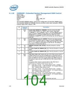
ESMRAMC—Extended System Management RAM Control
B/D/F/Type:
Address Offset:
Default Value:
Access:
0/0/0/PCI
9Eh
38h
RW/L, RWC, RO
8 bits
Size:
The Extended SMRAM register controls the configuration of Extended SMRAM space.
The Extended SMRAM (E_SMRAM) memory provides a write-back cacheable SMRAM
memory space that is above 1 MB.
Bit
Access &
Default
Description
7
RW/L
0b
Enable High SMRAM (H_SMRAME): This bit controls the SMM
memory space location (i.e., above 1 MB or below 1 MB) When
G_SMRAME is 1 and H_SMRAME is set to 1, the high SMRAM memory
space is enabled. SMRAM accesses within the range 0FEDA0000h to
0FEDBFFFFh are remapped to DRAM addresses within the range
000A0000h to 000BFFFFh. Once D_LCK has been set, this bit becomes
read only.
6
RWC
0b
Invalid SMRAM Access (E_SMERR): This bit is set when processor
has accessed the defined memory ranges in Extended SMRAM (High
Memory and T-segment) while not in SMM space and with the D-OPEN
bit = 0. It is software's responsibility to clear this bit. The software
must write a 1 to this bit to clear it.
5
4
RO
1b
SMRAM Cacheable (SM_CACHE): This bit is forced to 1 by the
GMCH.
RO
1b
L1 Cache Enable for SMRAM (SM_L1): This bit is forced to 1 by the
GMCH.
3
RO
1b
L2 Cache Enable for SMRAM (SM_L2): This bit is forced to 1 by the
GMCH.
2:1
TSEG Size (TSEG_SZ): Selects the size of the TSEG memory block if
enabled. Memory from the top of DRAM space is partitioned away so
that it may only be accessed by the processor interface and only then
when the SMM bit is set in the request packet. Non-SMM accesses to
this memory region are sent to DMI when the TSEG memory block is
enabled.
RW/L
00b
If Graphics stolen memory is placed above 4 GB, TSEG base is
determined as if graphics stoles memory size is 0.
00 = 1 MB TSEG. (TOLUD – GTT Graphics Memory Size – Graphics
Stolen Memory Size – 1 MB) to (TOLUD – GTT Graphics Memory
Size – Graphics Stolen Memory Size).
01 = 2 MB TSEG. (TOLUD – GTT Graphics Memory Size – Graphics
Stolen Memory Size – 2 MB) to (TOLUD – GTT Graphics Memory
Size – Graphics Stolen Memory Size).
10 = 8 MB TSEG. (TOLUD – GTT Graphics Memory Size – Graphics
Stolen Memory Size – 8 MB) to (TOLUD – GTT Graphics Memory
Size – Graphics Stolen Memory Size).
11 = Reserved.
Once D_LCK has been set, these bits becomes read only.
104
Datasheet

 INTEL [ INTEL ]