Ultra-Low Voltage Intel® Celeron® Processor — 650 MHz and 400 MHz
2.3
AGTL Signals
The ULV Intel®Celeron® processor system bus signals use a variation of the low-voltage swing
GTL signaling technology. The AGTL system bus depends on incident wave switching and uses
flight time for timing calculations of the AGTL signals, as opposed to capacitive derating. Intel
recommends analog signal simulation of the system bus including trace lengths. Contact your field
sales representative to receive the IBIS models for the Mobile Intel Celeron processor for
simulation.
The AGTL system bus of the ULV Intel Celeron processor is designed to support high-speed data
transfers with multiple loads on a long bus that behaves like a transmission line. However, in UP
embedded systems the system bus only has two loads (the processor and the chipset) and the bus
traces are short. It is possible to change the layout and termination of the system bus to take
advantage of this environment using the same AGTL I/O buffers. This termination is provided on
the processor core (except for the RESET# signal).
2.4
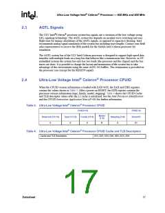
Ultra-Low Voltage Intel® Celeron® Processor CPUID
When the CPUID version information is loaded with EAX=01H, the EAX and EBX registers
contain the values shown in Table 3. After a power-on RESET, the EDX register contains the
processor version information (type, family, model, stepping). Table 4 shows the CPUID Cache
and TLB descriptor values after the L2 cache is initialized. See the Intel Processor Identification
and the CPUID Instruction Application Note AP-485 for further information.
Table 3. Ultra-Low Voltage Intel® Celeron® Processor CPUID
EAX[31:0]
EBX[7:0]
Model
[7:4]
Reserved [31:14]
Type [13:12]
Family [11:8]
Stepping [3:0]
Brand ID
X
0
6
B
X
01
Table 4. Ultra-Low Voltage Intel® Celeron® Processor CPUID Cache and TLB Descriptors
Cache and TLB Descriptors
01H, 02H, 03H, 04H, 08H, 0CH, 83H
Datasheet
17

 INTEL [ INTEL ]