Ultra-Low Voltage Intel® Celeron® Processor — 650 MHz and 400 MHz
Table 1. New and Revised Ultra-Low Voltage Intel® Celeron® Processor (0.13 µ) Signals
Signals
Function
BCLK,
BCLK#
Differential host clock signals.
CLKREF
BSEL[1:0]
DPSLP#
NCTRL
Host Clock reference signal in Single Ended Clocking mode.
Signals are output only instead of I/O. Refer to Section 3.2.3 for details.
Deep Sleep pin (replaces SLP# pin on the mobile Celeron processor (0.18 µ))
AGTL output buffer pull down impedance control.
Voltage Identification (different implementation from mobile Celeron processor (0.18 µ)). Refer
to Section 3.2.4 for details.
VID[4:0]
Power Good signal for VCCT, which indicates that, the VID signals are stable. Refer to Figure 4
for VTTPWRGD system level connections.
VTTPWRGD
2.2
Power Management
2.2.1
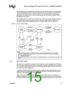
Clock Control Architecture
The ULV Intel® Celeron® processor clock control architecture (Figure 1) has been optimized for
leading edge computer designs. The clock control architecture consists of six different clock states:
Normal, Auto Halt, Quick Start, HALT/Grant Snoop and Deep Sleep states. The Auto Halt state
provides a low-power clock state that may be controlled through the software execution of the HLT
instruction. The Quick Start state provides a very low power and low exit latency clock state that
may be used for hardware controlled “idle” computer states. The Deep Sleep state provides
extremely low-power states that may be used for “Power-On-Suspend” computer states, which is
an alternative to shutting off the processor’s power. The exit latency of the Deep Sleep state is 30
ms in the Intel Celeron processor. Performing state transitions not shown in Figure 1 is neither
recommended nor supported. Figure 2 provides the clock state characteristics, which are described
in detail in the following sections.
2.2.2
2.2.3
Normal State
The Normal state of the processor is the normal operating mode where the processor’s core clock is
running and the processor is actively executing instructions.
Auto Halt State
This is a low-power mode entered by the processor through the execution of the HLT instruction. A
transition to the Normal state is made by a halt break event (one of the following signals going
active: NMI, INTR, BINIT#, INIT#, RESET#, FLUSH#, or SMI#).
Asserting the STPCLK# signal while in the Auto Halt state will cause the processor to transition to
the Quick Start state. Deasserting STPCLK# will cause the processor to return to the Auto Halt
state without issuing a new Halt bus cycle.
14
Datasheet

 INTEL [ INTEL ]