LXT362 — Integrated T1 LH/SH Transceiver for DS1/DSX-1 or PRI Applications
2.7
Diagnostic Mode Operation
The LXT362 offers multiple diagnostic modes as listed in Table 6. Note that various diagnostic
modes are only available in Host mode. In Hardware mode, the diagnostic modes are selected by a
combination of pin settings. In Host mode, the diagnostic modes are selected by writing
appropriate bits in the Diagnostic Control Register (DCR). The following paragraphs provide
details of the diagnostic modes.
Table 6. Diagnostic Mode Availability
Availability1
Hardware
Host Mode
Maskable2
Diagnostic Mode
Host
Loopback Modes
Local Loopback (LLOOP)
Analog Loopback (ALOOP)
Remote Loopback (RLOOP)
Yes
Yes
Yes
Yes
Yes
Yes
Yes
Yes
Yes
Yes
No
No
No
Yes
No
In-band Network Loopback (NLOOP)
Dual Loopback (DLOOP)
Internal Data Pattern Generation and Detection
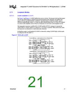
Transmit All Ones (TAOS)
Yes
Yes
Yes
Yes
No
Yes
No
Quasi-Random Signal Source (QRSS)
In-band Loop up/down Code Generator
Yes
No
Error Insertion and Detection
Bipolar Violation Insertion (INSBPV)
Logic Error Insertion (INSLER)
Yes
Yes
Yes
Yes
Yes
No
No
No
No
Yes
Bipolar Violation Detection (BPV)
Logic Error Detection, QRSS (QPD)
Yes
Yes
Alarm Condition Monitoring
Receive Loss of Signal (LOS) Monitoring
Yes
No
No
No
Yes
Yes
Yes
Yes
Yes
Yes
Yes
Yes
Receive Alarm Indication Signal (AIS) Monitoring
Transmit Driver Failure Monitoring—Open (DFMO)
Elastic Store Overflow and Underflow Monitoring
Other Diagnostic Reports
Receive Line Attenuation Indicator (LATN)
Built-In Self Test (BIST)
No
No
Yes
Yes
No
Yes
1. In Hardware mode, a combination of pin settings selects the Diagnostics Modes. In Host mode, writing appropriate bits in the
Control Registers selects the Diagnostic Modes.
2. Host mode allows interrupt masking by writing a “1” to the corresponding bit in the Interrupt Clear Register.
20
Datasheet

 INTEL [ INTEL ]