LXT362 — Integrated T1 LH/SH Transceiver for DS1/DSX-1 or PRI Applications
2.0
Functional Description
The LXT362 is a fully integrated, PCM transceiver for long- or short-haul, 1.544 Mbps (T1)
applications allowing full-duplex transmission of digital data over existing twisted-pair
installations. It interfaces with two twisted-pair lines (one pair each for transmit and receive)
through standard pulse transformers and appropriate resistors.
The figure on the front page of this data sheet shows a block diagram of the LXT362. The designer
can configure the device for either Host or Hardware control. In Host mode, control is via the serial
microprocessor port. In Hardware mode, individual pin settings allow stand-alone operation.
The transceiver provides a high-precision, crystal-less jitter attenuator. The user may place it in the
transmit or receive path, or bypass it completely.
The LXT362 meets or exceeds FCC, ANSI T1 and AT&T specifications for CSU and DSX-1
applications.
2.1
Initialization
During power up, the transceiver remains static until the power supply reaches approximately 3 V.
Upon crossing this threshold, the device begins a 32 ms reset cycle to calibrate the Phase Lock
Loops (PLL). The transceiver uses a reference clock to calibrate the PLLs: the transmitter reference
is TCLK, and the receiver reference clock is MCLK. MCLK is mandatory for chip operation and
must be an independent free running jitter free reference clock.
2.1.1
Reset Operation
A reset operation initializes the status and state machines for the LOS, AIS, NLOOP, and QRSS
blocks. In Hardware mode, holding pins RLOOP, LLOOP and TAOS High for at least one clock
cycle resets the device. In Host mode, writing a 1 to the bit CR2.RESET commands a reset which
clears all registers to 0. Allow 32 ms for the device to settle after removing all reset conditions.
2.2
Transmitter
2.2.1
Transmit Digital Data Interface
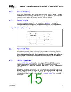
Input data for transmission onto the line is clocked serially into the device at the TCLK rate. TPOS
and TNEG are the bipolar data inputs. In Unipolar mode, the TDATA pin accepts unipolar data.
Input data may pass through either the Jitter Attenuator or B8ZS the encoder or both. In Host
mode, setting CR1.ENCENB = 1 enables B8ZS encoding. In Hardware mode, connecting the
MODE pin to Midrange selects zero suppression coding. With zero suppression enabled, the EC1
through EC4 inputs determine the coding scheme as listed in Table 10 on page 30.
TCLK supplies input synchronization. See the Figure 15 on page 41 for the transmit timing
requirements for TCLK and the Master Clock (MCLK).
14
Datasheet

 INTEL [ INTEL ]