LXT362 — Integrated T1 LH/SH Transceiver for DS1/DSX-1 or PRI Applications
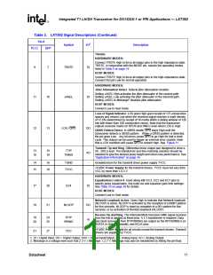
Table 3. LXT362 Signal Descriptions (Continued)
Pin #
Symbol
I/O1
Description
PLCC
QFP
22
29
GND
-
Ground return for power supply VCC.
HARDWARE MODES:
Equalization Control 1-3. EC1, EC2, and EC3 (along with the EC4 pin)
specify the pulse equalization, line build out and equalizer gain limit
settings. See Table 10 on page 30 for details.
HOST MODES:
Interrupt. INT goes Low to flag the host when LOS, AIS, NLOOP, QRSS,
DFMS or DFMO bits changes state, or when an elastic store overflow or
underflow occurs. To identify the specific interrupt, read the Performance
Status Register (PSR). To clear or mask an interrupt, write a one to the
appropriate bit in the Interrupt Clear Register (ICR). To re-enable the
interrupt, write a zero. INT is an open drain output that must be
connected to VCC through a pull-up resistor.
23
24
25
31
32
35
EC1 / INT
EC2 / SDI
EC3 / SDO
DI
DI
DI/O
Serial Data Input. SDI inputs the 16-bit serial address/command and data
word. SDI is sampled on the rising edge of SCLK. Timing is shown in
Figure 17 on page 43.
Serial Data Output. SDO outputs the 8-bit serial data read from the
selected LXT362 register. When the CLKE pin is High, SDO is valid on the
rising edge of SCLK. When CLKE is Low, SDO is valid on the falling edge
of SCLK. SDO goes to a high-impedance state when the serial port is
being written to or when CS is High. Timing is shown in Figure 18 on
page 43.
HARDWARE MODES:
Remote Loopback. When held High, the clock and data inputs from the
framer (TPOS/TNEG or TDATA) are ignored and the data received from
the twisted-pair line is transmitted back onto the line at the RCLK
frequency. Connect to Midrange2 to enable In-band Network loopback
detection (NLOOP).
26
36
RLOOP / CS
DI
HOST MODES:
Chip Select. CS is used to access the serial interface. For each read or
write operation, CS must transition from High to Low, and remain Low.
1. DI = Digital Input; DO = Digital Output; DI/O = Digital Input/Output; AI = Analog Input; AO = Analog Output.
2. Midrange is a voltage level such that 2.3 V ≤ Midrange ≤ 2.7 V. Midrange may also be established by letting the pin float.
12
Datasheet

 INTEL [ INTEL ]