IA186ES/IA188ES
Data Sheet
8-Bit/16-Bit Microcontrollers
November 15, 2011
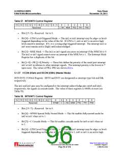
Table 57. INT2/INT3 Control Register
15 14 13 12 11 10
Reserved
9
8
7
6
5
4
3
2
1
0
LTM MSK PR2 PR1 PR0
Bits [15–5]—Reserved. Set to 0.
Bit [4]—LTM Level-Triggered Mode → The int2 or int3 interrupt may be edge- or level-
triggered depending on the value of this bit. If LTM is 1, int2 or int3 is an active high
level-sensitive interrupt. If 0, it is a rising-edge triggered interrupt. The interrupt int2 or
int3 must remain active (high) until acknowledged.
Bit [3]—MSK Mask → The int2 or int3 signal can cause an interrupt if the MSK bit is 0.
The int2 or int3 signal cannot cause an interrupt if the MSK bit is 1. The Interrupt Mask
Register has a duplicate of this bit.
Bit [2–0]—PR [2–0] Priority → These bits define the priority of the serial port interrupt
int2 or int3 in relation to other interrupt signals. The interrupt priority is the lowest at 7
upon reset. The values of PR2–PR0 are shown above.
5.1.37 I1CON (03ah) and I0CON (038h) (Master Mode)
INT0/INT1 CONtrol Register. IINT0 and INT1 are designated as interrupt type 0ch and 0dh,
respectively.
The int2 and int3 pins may be configured as the interrupt acknowledge pins inta0 and inta1,
respectively, the signals in cascade mode. The value of these registers is 000Fh at reset (see
Table 58).
Table 58. INT0/INT1 Control Register
15 14 13 12 11 10
Reserved
9
8
7
6
5
C
4
3
2
1
0
SFNM
LTM MSK PR2 PR1 PR0
Bits [15–7]—Reserved. Set to 0.
Bit [6]—SPNM Special Fully Nested Mode → This bit enables fully-nested mode for
int0 or int1 when set to 1.
Bit [5]—C Cascade Mode → This bit enables cascade mode for int0 or int1 when set
to 1.
Bit [4]—LTM Level-Triggered Mode → The int0 or int1 interrupt may be edge- or level-
triggered depending on the value of the bit. If LTM is 1, int0 or int1 is an active high
®
IA211050902-19
UNCONTROLLED WHEN PRINTED OR COPIED
http://www.innovasic.com
Customer Support:
Page 96 of 154
1-888-824-4184

 INNOVASIC [ INNOVASIC, INC ]