IA186ES/IA188ES
Data Sheet
8-Bit/16-Bit Microcontrollers
November 15, 2011
Comparisons are made between the count registers and maxcount registers and action taken
dependent on achieving the maximum count.
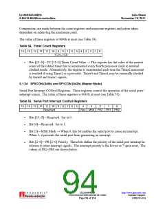
The value of these registers is 0000h at reset (see Table 54).
Table 54. Timer Count Registers
15 14 13 12 11 10
9
8
7
6
5
4
3
2
1
0
TC15–TC0
Bits [15–0]—TC [15–0] Timer Count Value → This register has the value of the current
count of the related timer that is incremented every fourth processor clock in internal
clocked mode. Alternatively, the register is incremented each time the Timer2 maxcount
is reached if using Timer2 as a prescaler. Timer0 and Timer1 may be externally clocked
by tmrin0 and tmrin1 signals.
5.1.34 SP0CON (044h) and SP1CON (042h) (Master Mode)
Serial Port Interrupt CONtrol Registers. These registers control the operation of the serial ports’
interrupt source. The value of these registers is 001Fh at reset (see Table 55).
Table 55. Serial Port Interrupt Control Registers
15 14 13 12 11 10
Reserved
9
8
7
6
5
4
3
2
1
0
Res MSK PR2 PR1 PR0
Bits [15–5]—Reserved. Set to 0.
Bit [4]—Reserved. Set to 1.
Bit [3]—MSK Mask → When 0, this bit enables the serial port to cause an interrupt.
When 1, it prevents the serial port from generating an interrupt.
Bits [2–0]—PR [2–0] Priority. These bits define the priority of the serial port interrupt in
relation to other interrupt signals. The interrupt priority is the lowest at 7 upon reset. The
values of PR2–PR0 are shown below.
®
IA211050902-19
UNCONTROLLED WHEN PRINTED OR COPIED
http://www.innovasic.com
Customer Support:
Page 94 of 154
1-888-824-4184

 INNOVASIC [ INNOVASIC, INC ]