IA186ES/IA188ES
Data Sheet
8-Bit/16-Bit Microcontrollers
November 15, 2011
Bit [5]—MC Maximum Count → When the timer reaches its maximum count, this bit is
set to 1 regardless of the interrupt enable bit. This bit may be used by software polling to
monitor timer status rather than through interrupts if desired.
Bits [4–1]—Reserved. Set to 0.
Bit [0]—CONT Continuous Mode Bit → The timer will run continuously when this bit is
set to 1. The timer will stop after each count run and EN will be cleared if this bit is set
to 0.
5.1.32 T2COMPA (062h), T1COMPB (05ch), T1COMPA (05ah), T0COMPB (054h), and
T0COMPA (052h)
Timer Maxcount COMpare Registers. These registers contain the maximum count value that is
compared to the respective count register. Timer0 and Timer1 have two of these compare
registers each.
If Timer0 and/or Timer1 is/are configured to count and compare firstly to register A and then
register B, the TMROUT0 or TMROUT1 signals may be used to generate various duty-cycle
wave forms.
Timer2 has only one compare register, T2COMPA.
If one of these timer maxcount compare registers is set to 0000h, the respective timer will count
from 0000h to FFFFh before generating an interrupt request. For example, a timer configured in
this manner with a 40-MHz clock will interrupt every 6.5536 µS.
The value of these registers is 0000h at reset (see Table 53).
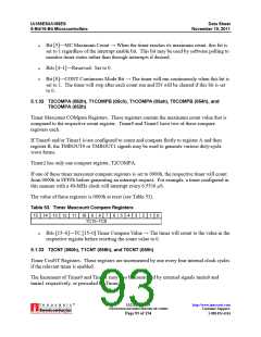
Table 53. Timer Maxcount Compare Registers
15 14 13 12 11 10
9
8
7
6
5
4
3
2
1
0
TC15–TC0
Bits [15–0]—TC [15–0] Timer Compare Value → The timer will count to the value in the
respective register before resetting the count value to 0.
5.1.33 T2CNT (060h), T1CNT (058h), and T0CNT (050h)
Timer CouNT Registers. These registers are incremented by one every four internal clock cycles
if the relevant timer is enabled.
The Increment of Timer0 and Timer1 may also be controlled by external signals tmrin0 and
tmrin1 respectively, or prescaled by Timer2.
®
IA211050902-19
UNCONTROLLED WHEN PRINTED OR COPIED
http://www.innovasic.com
Customer Support:
Page 93 of 154
1-888-824-4184

 INNOVASIC [ INNOVASIC, INC ]