Forced Quasi Resonant ZVS flyback controller
Functional Description
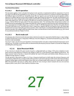
Vmfio is lower than 0.9V or input bulk voltage is lower than 150V (assuming RHV=100K). The jitter of current will
cause frequency jittering which improves the EMI spectrum signature.
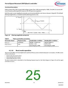
Both the peak current amplitude and peak current period will jitter over time as shown in Figure24. The default
jittering magnitude is ± 15.625mV and the jittering period is 1ms.
IPK + Ajitter_Max
Ajitter_Max / 10 points
Ipk
IPK - AjitterMax
t
100µs
Jitter Period = 10 points * 100µs = 1000µs
Figure 24 Jittering magnitude and period
Table 5
Peak current jitter parameters
Parameter Name
A_Jitter_max
Physical value
15.625mV
1ms
Enable jitter condition
Disable jitter condition
Vbulk>=175Vdc and
Vmfio>=1.0V,
Assuming RHV=100K
Vbulk<150Vdc or
Vmfio<0.9V,
Assuming RHV=100K
A_Jitter_period_val
4.2.10
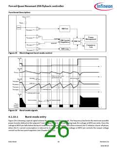
Burst mode operation
The burst mode (BM) is entered at light load to optimize efficiency and correlated total power consumption. The BM consists
of three main phases:
•
•
•
Burst mode entry (see 4.2.10.1)
Burst operation (see 4.2.10.2)
Burst mode exit (see 4.2.10.3)
The burst mode control is described in the following chapters based on the block diagram in Figure 26 and the signal
overview in 4.2.10.1.
Data Sheet
25
Revision 2.0
2020-08-20

 INFINEON [ Infineon ]