Forced Quasi Resonant ZVS flyback controller
Functional Description
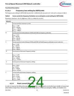
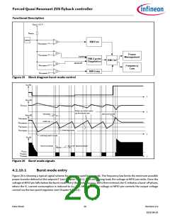
4.2.8.1
Frequency law setting for XDPS21081
The frequency law setting for XDPS21081 based on the is defined by the set point A, B, C ,D,E and F as shown in Table 4.
Table 4
Corner points for frequency limitation curve and peak current setting for XDPS21081
Assuming LL (low line) =72V, HL (high line) =372V, LPRI=200uH, RCS=0.135 Ω
Setpoint
A
B
C
Corner point for maximum current
V
MFIOA = 2.30V
f
SWmax = 145 kHz
V
V
CSmaxLL = 402mV
CSmaxHL = 368mV
Corner point for border between DCM3 and DCM2 for frequency reduction
V
MFIOB = 1.61V
f
SWB = 145 kHz
V
V
CSBLL = 336 mV
CSBHL = 303mV
Corner point for border between DCM2 and DCM1 for fixed frequency and peak current reduction
V
MFIOC = 2.30V
f
SWC = 120 kHz
V
V
CSCLL = 402mV
CSCHL = 368mV
D
Corner point at minimum frequency setting
V
MFIOD = 1.23V
f
SWD = 83.7 kHz
V
V
CSDLL = 260mV
CSminHL = 227mV
E
Corner point at minimum frequency setting
V
MFIOE = 0.86 V
f
SWE = 23 kHz
V
V
CSELL = 260mV
CSminHL = 227mV
F
Corner point at minimum frequency setting
V
MFIOF = 0.21V
f
SWmin = 23 kHz
V
V
CSminLL = 67mV
CSminHL = 33mV
4.2.9
Peak current jittering
In order to improve the EMI performance, the XDPS21081 enables peak current jittering at middle to heavy load
when Vmfio is larger than 1.0V and Input bulk voltage above 175Vdc (assuming RHV=100K), and disable once
Data Sheet
24
Revision 2.0
2020-08-20

 INFINEON [ Infineon ]