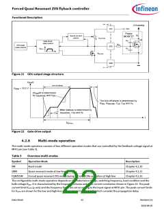
Forced Quasi Resonant ZVS flyback controller
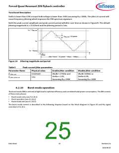
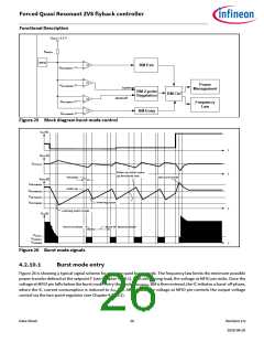
Functional Description
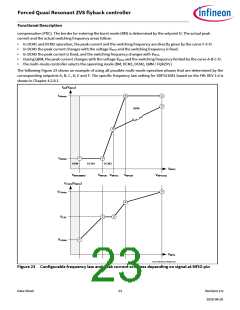
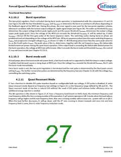
compensation (PDC). The border for entering the burst mode (BM) is determined by the setpoint D. The actual peak
current and the actual switching frequency areas follow:
•
•
•
•
•
In DCM1 and DCM2 operation, the peak current and the switching frequency are directly given by the curve F-E-D.
In DCM1 the peak current changes with the voltage VMFIO and the switching frequency is fixed.
In DCM2 the peak current is fixed, and the switching frequency changes with VMFIO
.
During QRM, the peak current changes with the voltage VMFIO and the switching frequency limited by the curve A-B-C-D.
the multi-mode controller selects the operating mode (BM, DCM1, DCM2, QRM / FQRZVS )
The following Figure 23 shows an example of using all possible multi-mode operation phases that are determined by the
corresponding setpoints A, B, C, D, E and F. The specific frequency law setting for XDPS21081 based on the FW: REV 1.0 is
shown in Chapter 4.2.8.1.
fSW(VMFIO
)
B
A
C
fSWmax
QRM
D
F
E
fSWmin
ABM
DCM1
DCM2
VMFIO
VMFIOBMEN
VCSPK(VMFIO
VMFIOD VMFIOC
VMFIOB
VMFIOmax
)
A
VCSmax
B
E
D
VCSC
F
VCSmin
VMFIO
MULTIMODE_FREQLAW
Figure 23 Configurable frequency law and peak current schemes depending on signal at MFIO pin
Data Sheet
23
Revision 2.0
2020-08-20

 INFINEON [ Infineon ]